A core mold for spinning parts with transverse internal ribs and a method of moving back and demoulding

A mandrel and horizontal technology, which is applied in metal processing equipment, forming tools, manufacturing tools, etc., can solve the problems of increasing labor intensity of workers, large shape and size of plywood, influence of workpiece forming quality and forming accuracy, and improve forming quality and forming accuracy, easy machining and assembly, and low labor intensity for workers

Active Publication Date: 2011-12-21
NORTHWESTERN POLYTECHNICAL UNIV
View PDF5 Cites 9 Cited by
  • Summary
  • Abstract
  • Description
  • Claims
  • Application Information

AI Technical Summary

Problems solved by technology

Due to the large shape, size and heavy weight of the mandrel head and splint for the spinning of large complex thin-walled shells, the difficulty of the demoulding process is further increased
Moreover, since the wall thickness of the workpiece is very thin, it is inevitable to scratch the inner wall of the workpiece or cause the workpiece to deform
In addition, every time a workpiece is formed by spinning, it is necessary to carry out such a complicated unloading work, and before spinning the next workpiece, it is necessary to carry out the combined installation and debugging of the mold again, thus prolonging the production cycle and reducing the cost. Production efficiency increases the production cost and increases the labor intensity of workers. Moreover, repeated mold unloading and installation and debugging of molds also have an impact on the forming quality and forming accuracy of the workpiece.

Method used


Image

  • A core mold for spinning parts with transverse internal ribs and a method of moving back and demoulding
  • A core mold for spinning parts with transverse internal ribs and a method of moving back and demoulding
  • A core mold for spinning parts with transverse internal ribs and a method of moving back and demoulding

Examples


Embodiment 1

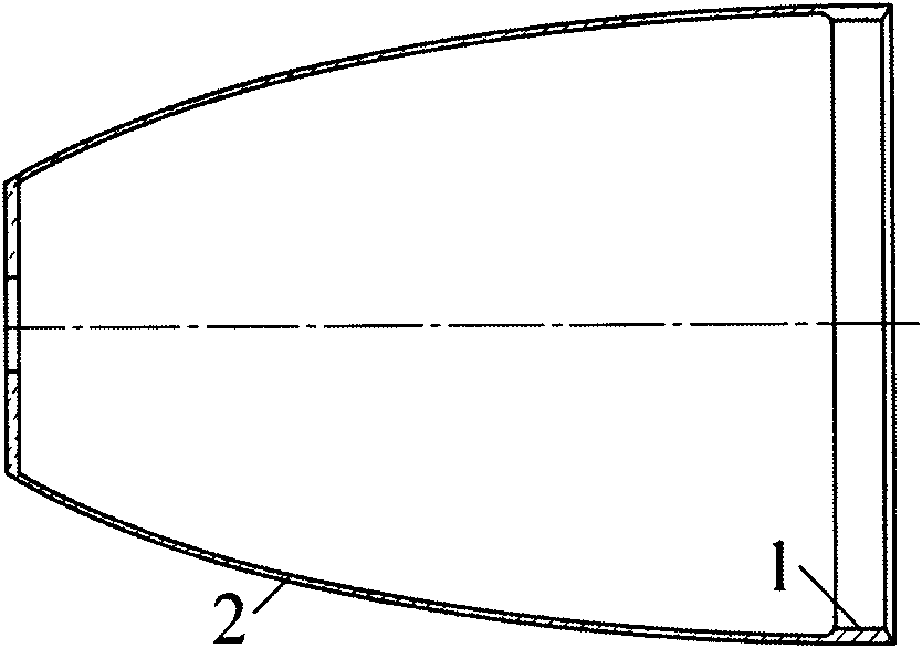
[0044] This implementation case is the horizontal and vertical combined split mandrel in the spin forming of a large complex thin-walled component with transverse inner ribs at the mouth of a certain spacecraft and the method of demoulding the spinning part with transverse inner ribs by moving the mold backward. The rib portion height of the workpiece rib portion 1 is between 2.5 and 2.8 mm, the axial length of the workpiece rib portion 1 is 15 mm, the axial length of the non-rib portion 2 of the workpiece is 343 mm, and the maximum diameter of the inner surface of the workpiece is 268.5 mm. The axial machining allowance of the workpiece is 30mm.

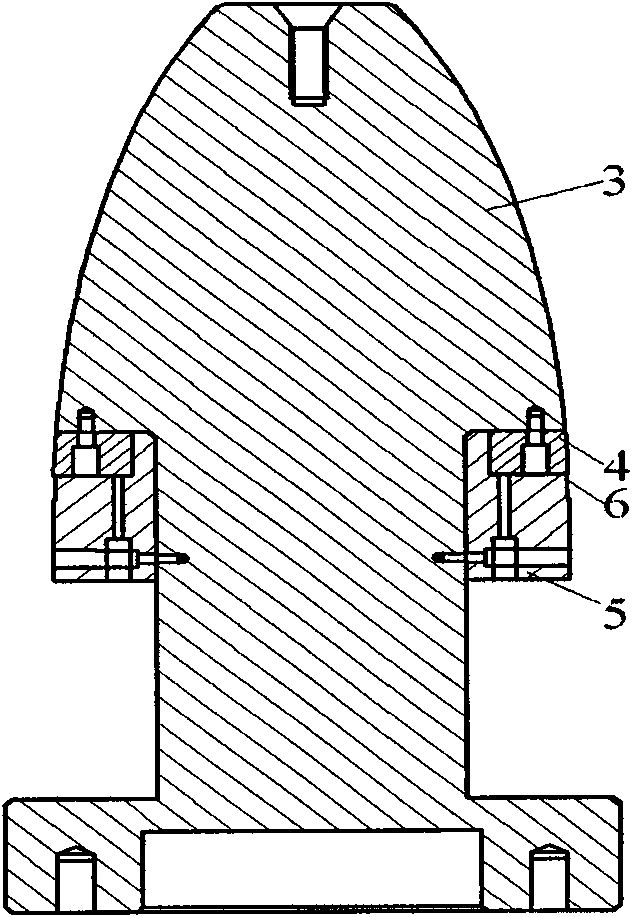
[0045] The spinning mandrel of this example includes a mandrel body 3 , a splint 4 and a collar 5 , wherein a mandrel groove 6 is located on the collar 5 , and the diameter of the mandrel groove 6 is 263.5 mm. The mandrel main body 3, the splint 4 and the collar 5 are all revolving bodies, and the splint 4 and the collar 5 are hollo...

Embodiment 2

[0054] This implementation case is the horizontal and vertical combined split mandrel in the spin forming of a large complex thin-walled component with transverse inner ribs at the mouth of a certain spacecraft and the method of demoulding the spinning part with transverse inner ribs by moving the mold backward. The rib portion height of the workpiece rib portion 1 is between 2.5 and 2.8 mm, the axial length of the workpiece rib portion 1 is 15 mm, the axial length of the non-rib portion 2 of the workpiece is 343 mm, and the maximum diameter of the inner surface of the workpiece is 268.5 mm. The axial machining allowance of the workpiece is 27.5mm.

[0055] The spinning mandrel of this example includes a mandrel body 3 , a splint 4 and a collar 5 , wherein a mandrel groove 6 is located on the collar 5 , and the diameter of the mandrel groove 6 is 263.5 mm. The mandrel main body 3, the splint 4 and the collar 5 are all revolving bodies, and the splint 4 and the collar 5 are hol...

Embodiment 3

[0064] This implementation case is the horizontal and vertical combined split mandrel in the spin forming of a large complex thin-walled component with transverse inner ribs at the mouth of a certain spacecraft and the method of demoulding the spinning part with transverse inner ribs by moving the mold backward. The rib portion height of the workpiece rib portion 1 is between 2.5 and 2.8 mm, the axial length of the workpiece rib portion 1 is 15 mm, the axial length of the non-rib portion 2 of the workpiece is 343 mm, and the maximum diameter of the inner surface of the workpiece is 268.5 mm. The axial machining allowance of the workpiece is 25mm.

[0065] The spinning mandrel of this example includes a mandrel body 3 , a splint 4 and a collar 5 , wherein a mandrel groove 6 is located on the collar 5 , and the diameter of the mandrel groove 6 is 263.5 mm. The mandrel main body 3, the splint 4 and the collar 5 are all revolving bodies, and the splint 4 and the collar 5 are hollo...


PUM


Abstract

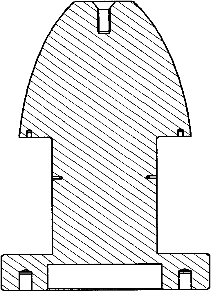
The invention relates to a mandrel for spinning a piece with a transverse inner rib and a backward moving demolding method of the mandrel. The outer shapes of a curved generatrix end of a mandrel main body and a clamping plate are curved generatrix shapes matched with the inner shape of a formed workpiece; the clamping plate is arranged on the outer side of a mounting surface formed by the large end face of the curved generatrix end of the mandrel main body; a ferrule is sleeved on a mandrel shaft; the small-diameter end of the ferrule is embedded between the clamping plate and the mandrel shaft of the mandrel main body and is attached to the mounting surface between the curved generatrix shaped end of the mandrel main body and the mandrel shaft; the small end face of the clamping plate is attached to the outer side of the mounting surface of the curved generatrix end of the mandrel main body; the arc surface of the excircle of the clamping plate is connected with the surface of the curved generatrix shaped end of the mandrel main body in a smooth mode; the large end face of the clamping plate is attached to the end face formed by a step on the surface of the outer circumference of the ferrule. A large complex curved generatrix thin-wall member spun workpiece with the transverse inner rib is demolded easily and conveniently, the forming quality and forming accuracy of the workpiece are improved, and the mandrel has the characteristics of short production period, high production efficiency, low production cost and low worker labor intensity.

Description

technical field [0001] The invention belongs to the field of spinning forming processing, and in particular relates to a mandrel for spinning of parts with transverse internal ribs and a method for moving back and demoulding. Background technique [0002] After decades of development, spinning technology is playing an increasingly important role in the near-net shape of thin-walled, complex-shaped, and lightweight integral components. Large complex curved generatrix thin-walled components are a type of parts commonly used in aerospace and weapon industries, such as aircraft engine covers, integral rocket engine components, compressor cones, nose cones of artificial satellites and missiles, and drug types in the weapon industry cover etc. The development of high-tech industries such as aerospace requires improving the strength and stiffness of such parts without affecting the aerodynamic performance of the exterior, so as to optimize the overall performance of aircraft, rock...

Claims


Application Information

Patent Timeline
Patent Type & Authority Applications(China)
IPC IPC(8): B21D37/10B21D22/16
Inventor 詹梅杨合江志强陈飞秦亚涛
Owner NORTHWESTERN POLYTECHNICAL UNIV
Why Eureka
Try Eureka