
Center knife rear type shield machine cutter head

A center knife and rear-mounted technology, which is applied in mining equipment, earthwork drilling, tunnels, etc., can solve the problems of limited excavation speed, large axial thrust, and reduced water content, so as to reduce axial thrust consumption and reduce axial thrust. thrust effect

Inactive Publication Date: 2011-12-21
TIANJIN UNIV
View PDF6 Cites 3 Cited by
  • Summary
  • Abstract
  • Description
  • Claims
  • Application Information

AI Technical Summary

Problems solved by technology

According to soil mechanics, the three-dimensional compressive stress state is not conducive to soil excavation, and the center cutter must exert a considerable axial thrust to complete soil excavation, so the total axial thrust of the cutterhead excavation is large
The problems brought about by the large axial thrust are: (1) Limiting the driving speed
(2) The soil corresponding to the center knife is squeezed away under the three-dimensional compressive stress state, and the soil becomes hard when the water content is reduced, and even forms a mud cake, making it difficult to excavate

Method used


Image

  • Center knife rear type shield machine cutter head
  • Center knife rear type shield machine cutter head
  • Center knife rear type shield machine cutter head

Examples


Embodiment Construction

[0009] The structure of the present invention will be further described below in conjunction with the accompanying drawings and through specific embodiments. It should be noted that this embodiment is descriptive and does not limit the protection content of the present invention.

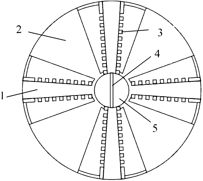
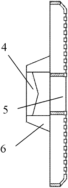
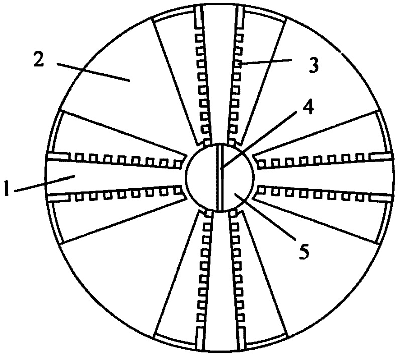
[0010] The cutter head of the shield machine with the center knife behind, including the knife beam 1, the width plate 2, the common excavation knife 3 and the center knife 4, etc., its structure is that there is a round hole 5 penetrating the cutter head in the center of the cutter head, and the center knife 4 is fixed behind the round hole of the cutterhead by the knife rest 6. The minimum distance between the cutting edge of the center knife 4 and the rear end face of the circular hole 5 is not less than half of the radius of the circular hole 5 . This kind of cutter head changes the stress state when the center cutter corresponds to the soil body being excavated, thereby greatly reducing the ax...


PUM


Abstract

The invention discloses a cutter head of a shield machine with a rear center knife. Its technical proposal is that the center knife in front of the traditional cutter head is removed, and a round hole is opened in the center of the cutter head through the cutter head, and the center knife is fixed by the tool holder. behind the round hole. The minimum distance between the center knife edge and the rear end face of the circular hole is not less than half of the radius of the circular hole. When the cutter head is working, the soil outside the central circular hole of the cutter head is first excavated by an ordinary excavating knife, and the soil in the central circular hole of the cutter head forms a soil cylinder and gradually passes through the circular hole. When the soil column hits the rear center cutter, because the confining soil without the surrounding soil is in a unidirectional compression state, it can be broken with only a small axial thrust. Therefore, the cutter head of the shield machine with the center knife behind can greatly reduce the axial thrust of the center knife, thereby reducing the total axial thrust, avoiding the phenomenon of soil cake during excavation, and improving the excavation efficiency.

Description

technical field [0001] The invention belongs to tunnel excavation equipment, in particular to a cutter head of a shield machine with a central knife placed at the rear of the cutter head. Background technique [0002] The shield machine is a mechanical device used for tunnel excavation, and the cutter head is the main part of the shield machine to excavate the soil. There are many types of excavation knives installed on the cutter head, among which the excavation knives located in the rotation center area of ​​the cutter head are called center knives, and other types of knives on the cutter head are collectively referred to as ordinary excavation knives. When working, the cutter head rotates and pushes forward to excavate the soil to realize tunnel excavation. The main loads of the cutterhead cutting soil are tangential force and axial thrust. Since the center knife is located at the rotation center of the cutter head, the tangential line speed is low, and the tangential f...

Claims


Application Information

Patent Timeline
IPC IPC(8): E21D9/08
Inventor 王燕群蔡宗熙亢一澜
Owner TIANJIN UNIV
Learn More