
A pointer positioning mechanism of a watch, its positioning method, and pointer zeroing and pointer correction methods

A pointer positioning and pointer technology, which is applied in the field of watches, can solve the problems of no installation space, cost and difficulty of positioning and installation, and achieve the effect of overcoming small installation space, great technical significance and commercial value, and simple and easy installation

Active Publication Date: 2011-12-21
东莞丝丽雅电子科技有限公司
View PDF6 Cites 35 Cited by
  • Summary
  • Abstract
  • Description
  • Claims
  • Application Information

AI Technical Summary

Problems solved by technology

However, there are some related technologies in the field of watches and clocks, such as the Chinese patent application 03113122.0 radio-wave clock movement positioning mechanism and its positioning method. The width of the ribs is sensed by the photoelectric component to judge the actual position of the pointer, so as to finally realize the automatic correction of the pointer; however, there is an insurmountable problem when this mechanism is used in watches: for watches, its internal space is far away. Smaller than a clock, as far as the smallest photoelectric component currently on the market is concerned, its volume is also larger than that of a watch’s gear, and it cannot be positioned by the gear ribs at all, and there is no installation space. Photoelectric components, the increased cost and the difficulty of positioning and installation will be unacceptable

Method used


Image

  • A pointer positioning mechanism of a watch, its positioning method, and pointer zeroing and pointer correction methods
  • A pointer positioning mechanism of a watch, its positioning method, and pointer zeroing and pointer correction methods
  • A pointer positioning mechanism of a watch, its positioning method, and pointer zeroing and pointer correction methods

Examples


Embodiment Construction

[0046] Below in conjunction with specific embodiment, the present invention will be further described:

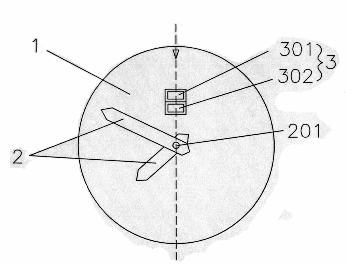
[0047] Such as figure 1 As shown, a pointer positioning mechanism of a watch includes a movement 1 and a pointer 2, the axis of each pointer 2 is located at the front center of the movement 1, and the movement 1 includes a microprocessor and is used to drive the pointer to rotate motor, and a reflective photoelectric sensor 3 mounted on the front of the movement 1 for capturing the signal of each pointer; wherein, the optical path of the reflective photoelectric sensor 3 points vertically to the place where each pointer 2 passes, and the reflective photoelectric sensor 3 The transmitting point 301, the receiving point 302 and the axis 201 of the pointer 2 are distributed in a straight line on the movement 1; the microprocessor recognizes the pointer according to the pointer signal captured by the reflective photoelectric sensor 3, and can control the The motor is running, ...


PUM


Abstract

The invention discloses a mechanism for positioning pointers of a watch and methods for positioning, resetting and calibrating the pointers and belongs to the technical field of the watch. The invention is technically characterized in that: an ordinary reflecting photoelectric sensor is arranged on the front surface of a movement of the watch and used for capturing pointer signals which are generated during the sweeping of the pointers; a microprocessor processes the pointer signals; a filtering module of the microprocessor performs correlation filtering on the pointer signals to improve the signal to noise ratio of the pointer signals; a pointer identification module performs statistic analysis and characteristic analysis on the pointer signals to determine the position of each pointer; and a motor control module controls the pointers to move according to the position of each pointer, so that the pointers can be automatically calibrated and reset. In the scheme, an ordinary process installation requirement is only required without designing of a special detection component, so that a technology for automatically calibrating the pointers of the watch can be popularized and applied on a large scale, the cost of products can be greatly reduced, and the invention has an important technical significance and a business value.

Description

technical field [0001] The invention relates to the technical field of watches, in particular to a watch pointer positioning mechanism, a watch pointer positioning method, a pointer reset method and a pointer correction method. Background technique [0002] One of the development trends of high-end clocks and watches is the automation of precise timing and operation. In high-end clocks and watches, pointer indication or dual pointer and digital indication are generally used, and quartz clock technology is often used to ensure the accuracy of self-timekeeping. The clock is equipped with a crystal oscillator inside, and the system time is generated by the crystal oscillator, and then the system time is converted into the stepping time of the motor through calculation, that is, the pointer predicts the time, and then is transmitted to the pointer through the gear, that is, the pointer displays the time. After calibration, the above three times are synchronized, but the positi...

Claims


Application Information

Patent Timeline
IPC IPC(8): G04C9/02G04G5/00G04R40/00
Inventor 黄向峰
Owner 东莞丝丽雅电子科技有限公司
Learn More