A cooling device for improving the power generation capacity of photovoltaic cells

A photovoltaic cell and cooling device technology, applied in photovoltaic power generation, photovoltaic modules, circuits, etc., can solve the problems of burning out chips, reducing power generation efficiency, water and electricity consumption, etc., achieving strong heat absorption and heat dissipation capabilities, efficient and rapid heat dissipation. The effect of reducing and improving the power generation capacity

Inactive Publication Date: 2011-12-21
袁长胜
View PDF6 Cites 3 Cited by
  • Summary
  • Abstract
  • Description
  • Claims
  • Application Information

AI Technical Summary

Problems solved by technology

[0002] During the normal operation of the photovoltaic power generation module, the light energy projected onto the chip (photovoltaic cell), except partly converted into electrical energy, most of the remaining energy is converted into heat energy, which must be taken away from the chip and released to the atmosphere immediately. In order to protect the normal operation of the components, otherwise, the temperature difference between the inside and outside of the chip will decrease, which will reduce the power generation efficiency, and even the high temperature will burn the chip and cannot continue to generate electricity
The existing chip cooling methods mainly include water cooling, forced ventilation cooling and natural cooling. Water cooling requires water and power consumption; forced ventilation cooling requires power consumption, and it is difficult to achieve efficient cooling; Photovoltaic power generation components need to dissipate a large amount of heat
Therefore, the efficient heat dissipation of photovoltaic cells is one of the core issues restricting the power generation capacity of existing batteries. Under the existing heat dissipation capacity, the optimal power generation components can only meet the power generation requirements of about 500 to 600 times the light concentration. Far from meeting the needs of use

Method used


Image

  • A cooling device for improving the power generation capacity of photovoltaic cells
  • A cooling device for improving the power generation capacity of photovoltaic cells
  • A cooling device for improving the power generation capacity of photovoltaic cells

Examples


Embodiment Construction

[0016] The present invention will be further explained below in conjunction with the accompanying drawings.

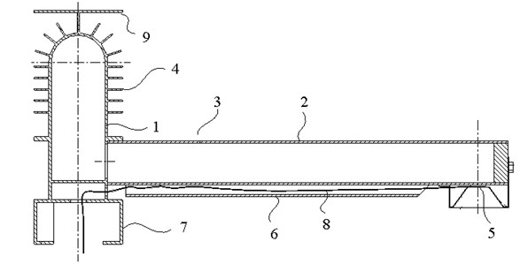
[0017] like figure 1 As shown, the cooling device for improving the power generation capacity of photovoltaic cells is a T-shaped heat dissipation pipe 3 composed of interconnected main pipes 1 and side pipes 2; a cooling medium is passed through the T-shaped heat dissipation pipe 3, and cooling fins are provided on the main pipe 1 The sheet 4 is provided with a bracket 5 for placing photovoltaic cells on the side pipe 2 . A sun visor 9 is provided on the main pipe 1 . The bracket 5 is arranged under the side pipe 7 , and the side pipe 2 is provided with a hole 6 for placing the conductive wire 8 of the photovoltaic cell. A junction box 7 is provided below the main pipe 1 .

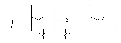
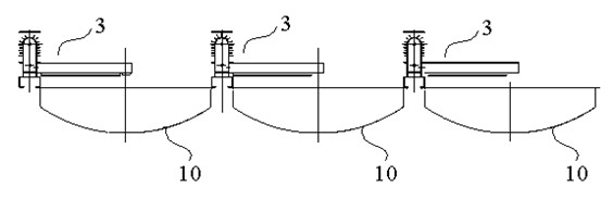
[0018] like figure 2 and image 3 As shown, in actual use, the number of T-shaped cooling pipes 3 can be set according to the number of modules. When there is only one reflecting mirror 10,...


PUM


Abstract

The invention discloses a cooling device for improving the power generation capacity of photovoltaic cells, which is a T-shaped radiating pipe composed of a main pipe and at least one side pipe that communicate with each other; The fins are provided with brackets for placing photovoltaic cells on the side tubes. Compared with the existing solar tracker, the cooling device for improving the power generation capacity of the photovoltaic cell of the present invention has outstanding advantages including: due to the use of the heat pipe heat transfer principle in which the two phases of the cooling medium alternately change under high vacuum conditions, the The cooling device has the characteristics of quick start of the cooling process, small temperature difference between the cooling end (main pipe) and the heating end (side pipe), so that both ends have strong heat absorption and heat dissipation capabilities, and the heat on the photovoltaic cells can be dissipated efficiently and quickly, which will effectively guarantee Photovoltaic power generation components have high conversion efficiency and long service life. After testing, the cooling device can meet the use requirements of 1000 times of light concentration, which greatly improves the power generation capacity of photovoltaic cells.

Description

technical field [0001] The invention relates to a photovoltaic power generation device, in particular to a cooling device for improving the power generation capacity of photovoltaic cells. Background technique [0002] During the normal operation of the photovoltaic power generation module, the light energy projected onto the chip (photovoltaic cell), except partly converted into electrical energy, most of the remaining energy is converted into heat energy, which must be taken away from the chip and released to the atmosphere immediately. In order to protect the normal operation of the components, otherwise, the temperature difference between the inside and outside of the chip will decrease, which will reduce the power generation efficiency, and even the high temperature will burn out the chip and cannot continue to generate electricity. The existing chip cooling methods mainly include water cooling, forced ventilation cooling and natural cooling. Water cooling requires wate...

Claims


Application Information

Patent Timeline
Patent Type & Authority Applications(China)
IPC IPC(8): H01L31/052H02S40/42
CPCY02E10/50
Inventor 袁长胜张志坚谢泽民
Owner 袁长胜
Why Eureka
Try Eureka