
Power regulating circuit of non-contact type energy transmission system and control method thereof

An energy transmission and non-contact technology, which is applied in the direction of circuit devices, electromagnetic wave systems, electrical components, etc., can solve the problems that the boost chopper circuit cannot reduce the voltage and the output power cannot be increased, and achieve superior implementation effects, The circuit structure and control algorithm are simple, and the circuit structure is simple

Active Publication Date: 2014-04-30
重庆艾普特电气有限公司
View PDF3 Cites 0 Cited by
  • Summary
  • Abstract
  • Description
  • Claims
  • Application Information

AI Technical Summary

Problems solved by technology

However, there are some shortcomings in the above three methods
For the two methods of accessing the step-down chopper circuit and decoupling, if the power picked up by the secondary circuit is relatively low, and the load needs to output more power, no matter how the duty cycle is adjusted, the system’s The output power will never be able to increase
For the method of connecting the boost chopper circuit, when the secondary circuit voltage increases with the change of the load, the boost chopper circuit cannot achieve the purpose of reducing the voltage

Method used


Image

  • Power regulating circuit of non-contact type energy transmission system and control method thereof
  • Power regulating circuit of non-contact type energy transmission system and control method thereof
  • Power regulating circuit of non-contact type energy transmission system and control method thereof

Examples


Embodiment Construction

[0031] The present invention will be described in further detail below in conjunction with the accompanying drawings and specific embodiments.

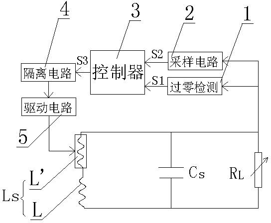
[0032] Such as figure 2 As shown: a power regulation circuit of a non-contact energy transmission system proposed by the present invention, including a pickup coil Ls, a tuning capacitor Cs, and a load RL. The pickup coil Ls and the tuning capacitor Cs form a secondary resonance circuit to realize energy pickup and transmit the picked-up energy to the load RL, the pickup coil Ls is composed of a fixed inductance L and a variable inductance L' connected in series, and the input value of the variable inductance L' is determined by the controller 3 control, the input end of the controller 3 is provided with a zero-crossing detection circuit 1 and a sampling circuit 2, the detection point of the zero-crossing detection circuit 1 and the sampling point of the sampling circuit 2 are connected to the high level end of the load RL, The zero...


PUM


Abstract

The invention discloses a power regulating circuit of a non-contact type energy transmission system, which comprises a pickup coil, a tuning capacitor and a load and is characterized in that the pickup coil is formed by connecting a fixed inductance and a variable inductance in series, wherein the access value of the variable inductance is controlled by a controller; an input end of the controller is provided with a zero passage detecting circuit and a sampling circuit; an output end of the controller is also provided with an isolating circuit and a driving circuit; and a control method of the controller comprises the following steps of: determining the access value of the variable inductance by comparing the sizes of sampling voltage values in the previous period and in the next period, and finally enabling a secondary pickup voltage to be stable at a fixed value or fluctuate between two values by circularly comparing a front periodic voltage and a back periodic voltage. The power regulating circuit has the obvious effects: the circuit has a simple structure, a control algorithm is easy to implement, the system has better dynamic response speed, stability and anti-interference performance, and the effective pickup of power can be ensured in a load changing process so as to realize the maximum energy transmission of the system.

Description

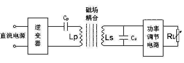
technical field [0001] The invention relates to a non-contact energy transmission technology, in particular, a power regulation circuit of a non-contact energy transmission system and a control method thereof. Background technique [0002] With the development of science and technology, non-contact energy transmission technology has been widely used, such as non-contact power supply of high-power electrical equipment, non-contact charging of low-power portable electronic devices, non-contact power supply of electrical equipment working in special environments, etc. . This technology has broad application prospects due to its advantages of no contact spark, no device wear, easy maintenance, good safety performance, low noise, and high degree of automation. [0003] Such as figure 1 As shown, the non-contact energy transmission system is mainly composed of a primary loop and a secondary loop, also called the primary loop and the secondary loop. Usually the primary circuit i...

Claims


Application Information

Patent Timeline
Patent Type & Authority Patents(China)
IPC IPC(8): H02J17/00H02J50/12
Inventor 王智慧孙跃戴欣唐春森苏玉刚
Owner 重庆艾普特电气有限公司
Learn More