A kind of isolated transmission method and circuit of switching power supply

A switching power supply and transmission circuit technology, applied in electrical components, adjusting electrical variables, output power conversion devices, etc., can solve the problems of poor radiation resistance, small transmission ratio, unfavorable loop stability, etc., and achieve strong radiation resistance. , high reliability, easy debugging effect

Inactive Publication Date: 2011-12-21
MORNSUN GUANGZHOU SCI & TECH
View PDF3 Cites 16 Cited by
  • Summary
  • Abstract
  • Description
  • Claims
  • Application Information

AI Technical Summary

Problems solved by technology

[0004] However, this traditional way of using optocoupler isolation to transmit small signals has the following disadvantages: 1. After the ambient temperature changes, the transmission ratio is seriously affected, which makes the control loop of the power supply out of control; 2. The transmission ratio is small, which is not conducive to loop stability. ; 3. Poor radiation resistance, relevant data show that the total dose of optocoupler radiation resistance does not exceed 3*10 4 rad(si)
[0005] In aerospace, military industry, communication and other fields, switching power supplies generally work in a closed and high-temperature environment. In this way, there are high requirements for the stability and power derating of power supply products. The error signal method does not apply

Method used


Image

  • A kind of isolated transmission method and circuit of switching power supply
  • A kind of isolated transmission method and circuit of switching power supply
  • A kind of isolated transmission method and circuit of switching power supply

Examples


Embodiment Construction

[0022] The present invention will be further described in detail below in conjunction with the accompanying drawings and specific embodiments.

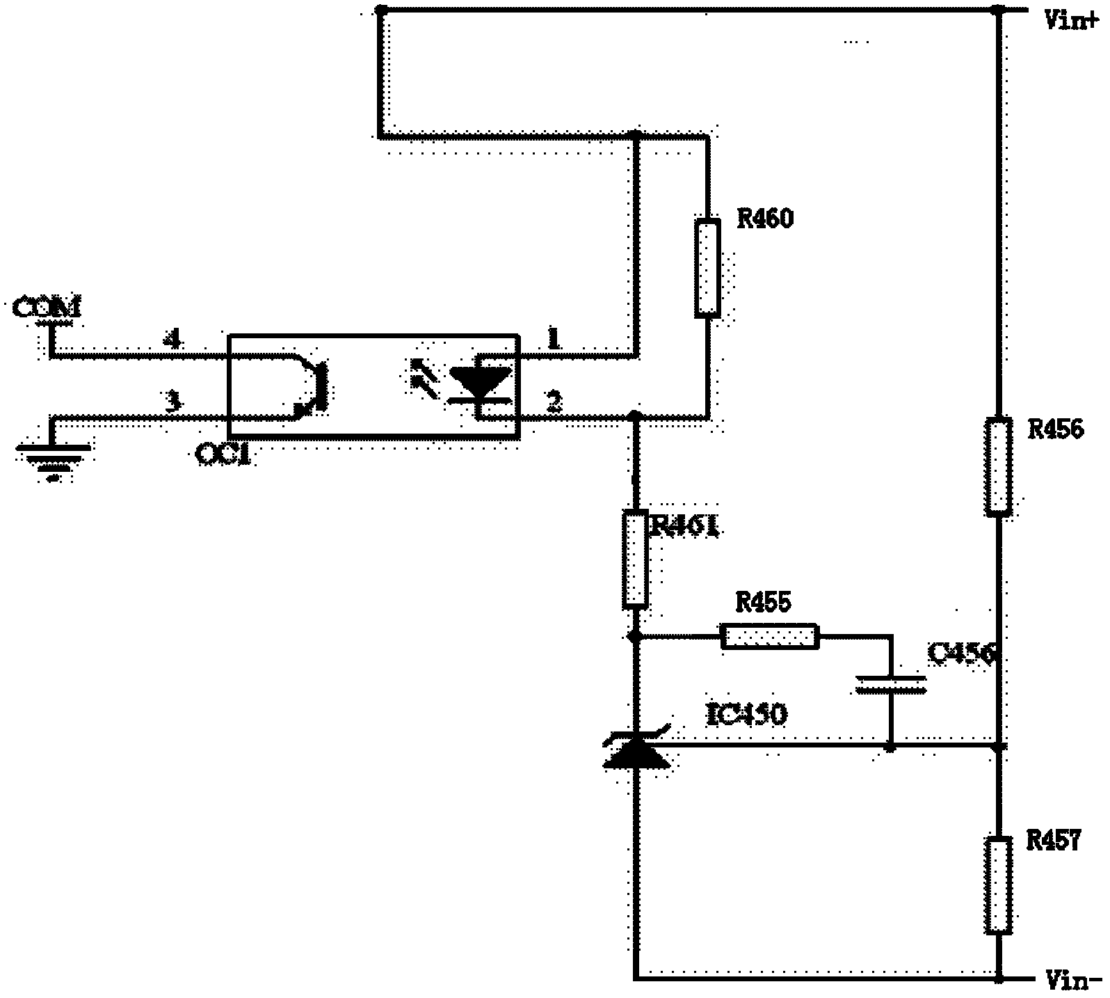
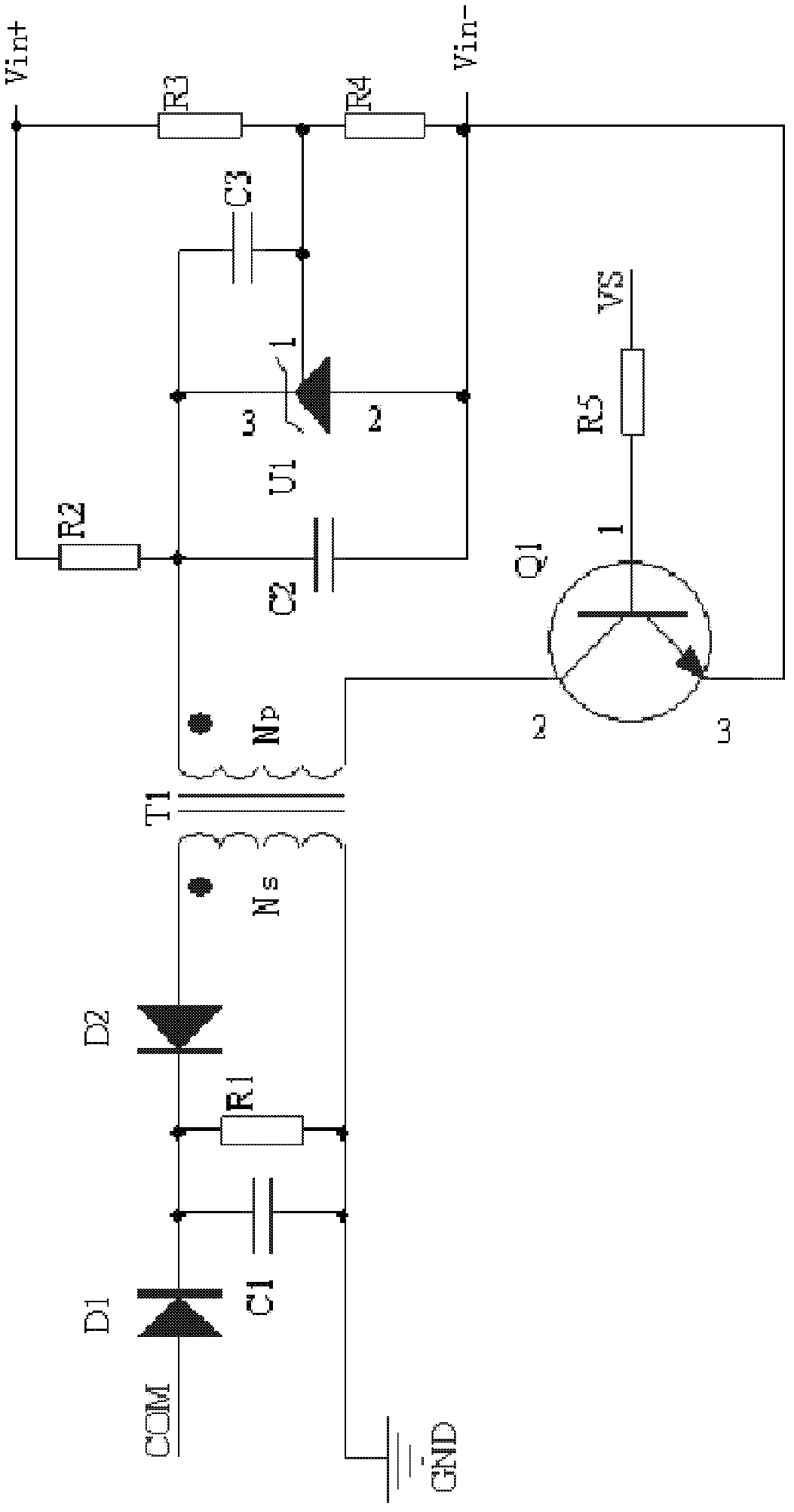
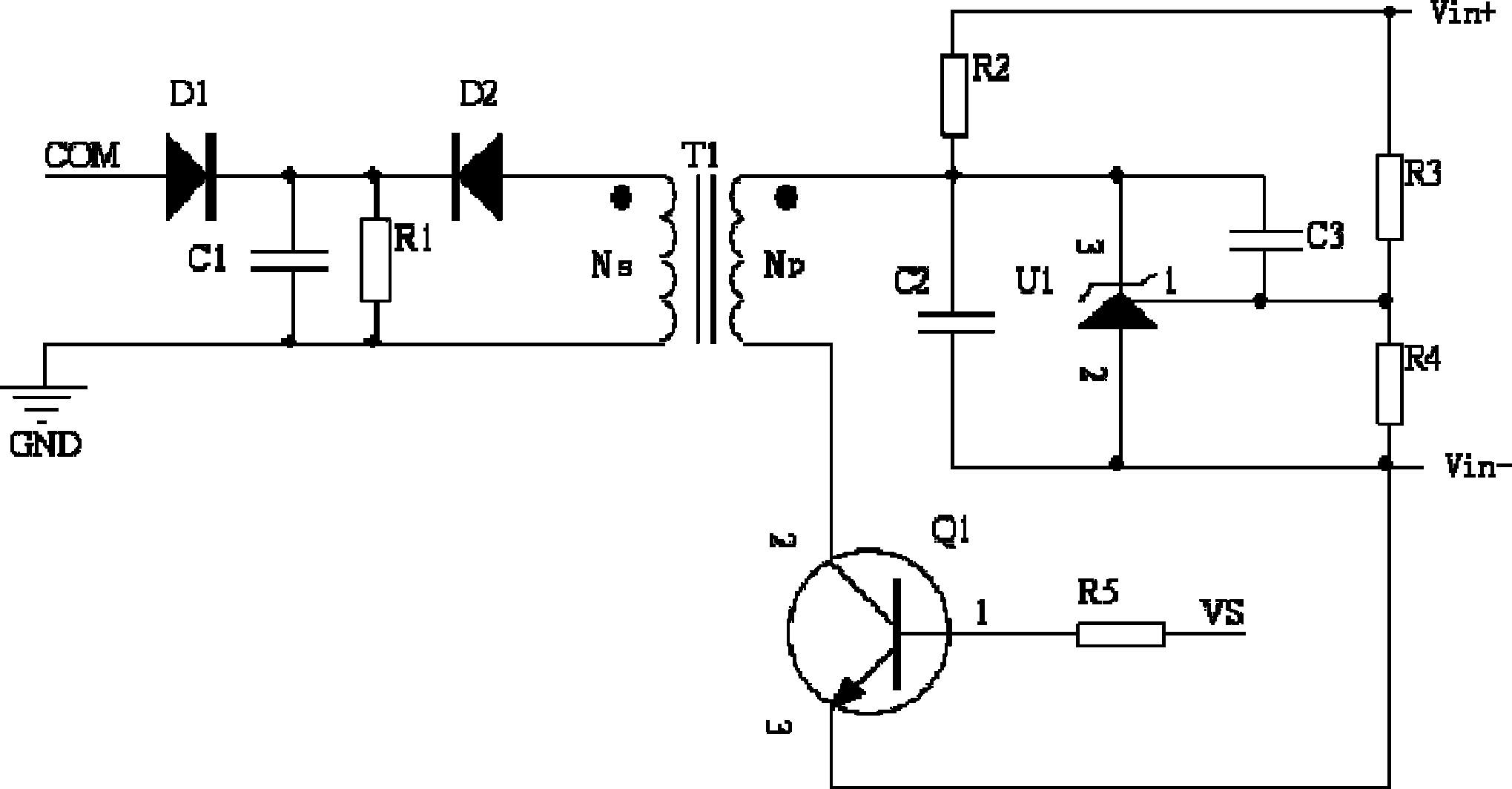
[0023] figure 2 The isolated transmission circuit according to Embodiment 1 of the present invention is shown, including a sampling circuit, an isolation circuit and a rectification and filtering circuit.

[0024] The isolation circuit includes an isolation transformer T1, a driving transistor Q1, a current limiting resistor R5 and a pulse signal source VS; the pulse signal source VS is connected to the base 1 of the driving transistor Q1 through the current limiting resistor R5, and the emitter 3 of the driving transistor Q1 is connected to the isolation The input voltage reference terminal Vin- of the transmission circuit, the collector 2 of the driving transistor Q1 is connected to the opposite end of the primary winding Np of the isolation transformer T1; the pulse signal source VS outputs a pulse signal with a fixed frequency an...


PUM


Abstract

The invention discloses an isolation transmission method of a switching power supply and a circuit thereof. Error signals sampled by a sampling circuit are sequentially output through an isolation circuit and a rectification filter circuit; the isolation circuit is composed of an isolation transformer, a driving triode and a pulse signal source, and the pulse The signal source outputs a pulse signal with a fixed frequency and pulse width, and the pulse signal is mixed with the error signal output by the sampling circuit through the driving triode in the primary winding of the isolation transformer, and the mixed signal is output from the secondary winding of the isolation transformer to the rectification filter circuit, It is rectified and filtered by a rectifying and filtering circuit to output a DC level signal whose amplitude is controlled by an error signal; the isolated transmission method and its circuit of the present invention have high transmission ratio for transmitting small signals, are less affected by temperature changes, and are resistant to radiation With the characteristics of strong capability, good stability and high derating, it is suitable for applications in high and harsh environments such as aerospace, military industry, and communications.

Description

technical field [0001] The invention relates to an isolated transmission method and a circuit thereof, in particular to a switching power supply isolation transmission method and a circuit thereof suitable for application in severe environments such as aerospace, military industry, and communication. Background technique [0002] In the prior art, in order to achieve the purpose of stabilizing the output voltage of the switching power supply, the error signal is sampled on the secondary side of the switching power supply. After the signal is amplified by the error amplifier, it is converted into a current signal and output to the primary side of the switching power supply through optocoupler isolation. Chip, in order to realize the feedback control of the drive signal of the switch tube. [0003] figure 1 A specific isolated transmission circuit of the feedback control method is shown, wherein the first voltage dividing resistor R456, the second voltage dividing resistor R4...

Claims


Application Information

Patent Timeline
Patent Type & Authority Applications(China)
IPC IPC(8): H02M3/315
Inventor 李绍兵倪远
Owner MORNSUN GUANGZHOU SCI & TECH
Why Eureka
Try Eureka