Parameter Identification Method of Asynchronous Motor Based on Adaptive Compensation

A self-adaptive compensation, asynchronous motor technology, applied in the control of generators, motor generator control, electronic commutation motor control, etc., can solve the problems of poor generality of motor parameter identification methods, and achieve the effect of high accuracy and improved identification accuracy

Inactive Publication Date: 2011-12-21
哈尔滨同为电气股份有限公司 +1
View PDF4 Cites 49 Cited by
  • Summary
  • Abstract
  • Description
  • Claims
  • Application Information

AI Technical Summary

Problems solved by technology

[0004] The purpose of the present invention is to solve the problem of poor versatility of the existing motor parameter identification method, and to provide an asynchronous motor parameter identification method based on adaptive compensation

Method used


Image

  • Parameter Identification Method of Asynchronous Motor Based on Adaptive Compensation
  • Parameter Identification Method of Asynchronous Motor Based on Adaptive Compensation
  • Parameter Identification Method of Asynchronous Motor Based on Adaptive Compensation

Examples


specific Embodiment approach 1

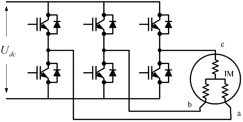
[0020] Specific implementation mode one: the following combination figure 1 Describe this embodiment, this embodiment is realized based on described motor and the inverter connected with this motor input end, and it comprises the following steps:

[0021] Step 1: Test the motor, obtain the DC bus voltage of the inverter and the PWM duty cycle of each phase, and reconstruct the reference input voltage of each phase of the motor;

[0022] Step 2: Calculate according to the reference input voltage of each phase of the motor reconstructed in step 1, and obtain the identification value R of the stator resistance value of each phase of the motor S ;

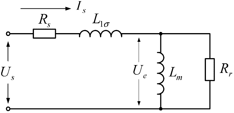
[0023] Step 3: Use the single-phase AC method to test the motor, control the amplitude and phase of the current injected into the motor through the current closed-loop PI regulator, obtain the DC bus voltage of the inverter and the PWM duty cycle of each phase at this time, and reconstruct the motor The reference input voltage U of e...

specific Embodiment approach 2

[0026] Specific Embodiment Two: This embodiment is a further description of Embodiment One. In step two, the identification value R of the stator resistance value of each phase of the motor is obtained. S The specific method is: use the DC method to test the motor, inject two DC currents of different sizes through the inverter between any two-phase windings of the motor, and the size of the DC current is controlled by the PI regulator. The two-phase winding current value I T1 , I T2 And the reference input voltage value U of the two-phase winding of the motor obtained by reconstruction T1 , U T2 , using the following formula:

[0027] U T 1 - ΔU I T 1 = U T 2 ...

specific Embodiment approach 3

[0041] Embodiment 3: This embodiment is a further description of Embodiment 1 or 2. The specific method for calculating and obtaining the real part and the imaginary part of the reference input voltage fundamental wave of each phase of the motor in step 3 is:

[0042] Set the reference value i of the AC current signal input by the PI regulator control ref * for: i ref * =I A sin(ωt),

[0043] where I A is the amplitude of the alternating current signal, ω is the angular frequency of the alternating current signal, t is the time,

[0044] The PI controls the output voltage signal u sα for:

[0045] u sα =U A sin(ωt+θ),

[0046] where U A is the voltage signal u sα The amplitude of , θ is the voltage signal u sα with the reference value of the current signal i ref * At the moment when the current phase of the motor is zero, the real part U of the fundamental wave of the reference input voltage of each phase of the motor is obtained by Fourier transform calculation...


PUM


Abstract

The invention discloses an adaptive-compensation-based asynchronous motor parameter recognition method, which belongs to the technical field of static parameter recognition of asynchronous motors and solves the problem of low universality of the conventional motor parameter recognition method. The method comprises the following steps of: recognizing stator resistance values of each phase of the motor, testing the motor by using a single-phase AC method to reconstruct the reference input voltage of each phase of the motor, performing Fourier transform on the reconstructed reference input voltage of each phase of the motor in a current cycle, and performing calculation to obtain real parts and virtual parts of fundamental waves of the reference input voltage of each phase of the motor; performing calculation to obtain error voltage between the reference input voltage and actual input voltage of each phase of the motor, and obtaining the real part and virtual part of the fundamental waveof the error voltage; and performing calculation to obtain the leakage inductance, rotor resistance and mutual inductance of each phase of the motor. The method is applied to the parameter recognition of the asynchronous motor.

Description

technical field [0001] The invention relates to an asynchronous motor parameter identification method based on self-adaptive compensation, and belongs to the technical field of asynchronous motor static parameter identification. Background technique [0002] With the development of vector control algorithm and direct torque control algorithm, asynchronous motor frequency conversion speed regulation system has been more widely used in the industry. This kind of control algorithm relies on the mathematical model of the motor to realize, and its control performance depends directly on the accuracy of the motor parameters. Some motor parameters calculated from the data on the nameplate of the asynchronous motor or the data in the product manual usually have large deviations. If the motor parameters are inaccurate, the magnetic field orientation will be inaccurate, the energy consumption of the system will increase, the output of the motor will decrease, and the efficiency will ...

Claims


Application Information

Patent Timeline
Patent Type & Authority Applications(China)
IPC IPC(8): H02P21/14
Inventor 陈伟于泳徐殿国王高林杨荣峰
Owner 哈尔滨同为电气股份有限公司
Why Eureka
Try Eureka