
Method for Obtaining Accurate Wire Transmission Delay in Time Synchronization

A technology of transmission delay and time synchronization, applied in the field of data communication, it can solve the problems of inability to obtain the delay, the accuracy cannot meet the requirements, and the system cannot calculate the one-way or two-way accurate delay, so as to meet the normal operation and ensure the accurate time. Synchronized effect

Active Publication Date: 2011-12-21
FENGHUO COMM SCI & TECH CO LTD
View PDF1 Cites 21 Cited by
  • Summary
  • Abstract
  • Description
  • Claims
  • Application Information

AI Technical Summary

Problems solved by technology

[0006] However, when the software method can interact with timestamps but the accuracy cannot meet the requirements, and the hardware method can provide high-precision timestamps but cannot interact with timestamps, the system cannot calculate the one-way or two-way precise delay, and there is no way to obtain the delay. It is impossible to compensate for the delay, which leads to the system time being out of sync. For the entire network, the accumulation of delay will also cause the normal operation of the business

Method used


Image

  • Method for Obtaining Accurate Wire Transmission Delay in Time Synchronization
  • Method for Obtaining Accurate Wire Transmission Delay in Time Synchronization
  • Method for Obtaining Accurate Wire Transmission Delay in Time Synchronization

Examples


Embodiment Construction

[0030] The present invention will be described in further detail below in conjunction with the accompanying drawings and embodiments.

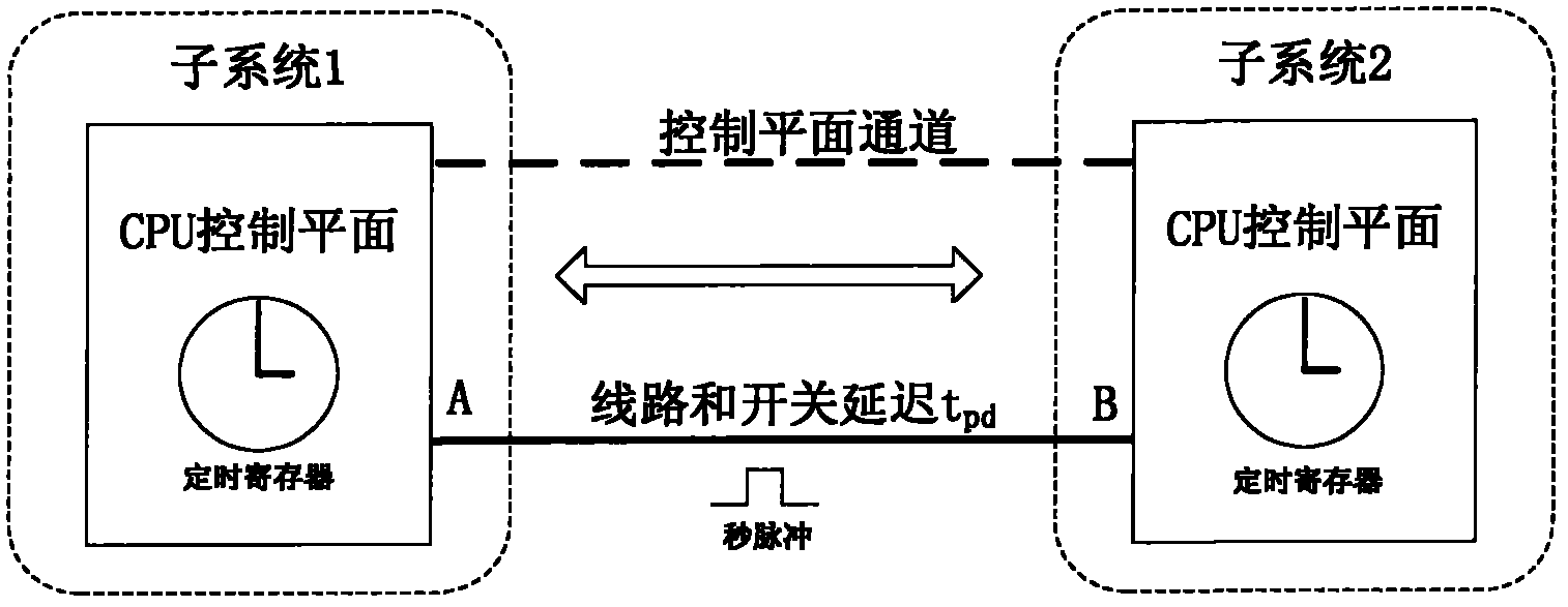
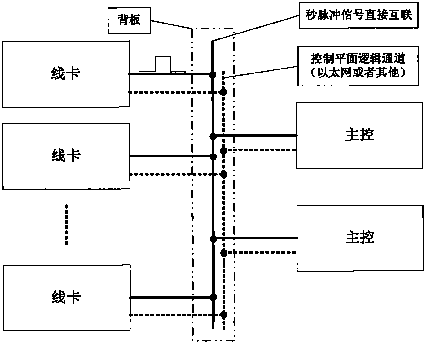
[0031] Such as figure 2As shown, it is a schematic diagram of a distributed rack-type communication system applied in the embodiment of the present invention, which includes two main control units with large-capacity switching capabilities, and is responsible for communication data plane data exchange; at the same time, the system control plane CPU unit is also The main control unit is responsible for system configuration and calculation of distributed communication protocols. The distributed rack-mounted communication system uses PTP for precise time synchronization, and the backplane performs direct physical interconnection of each unit (ie, line card) through second pulses, and the control plane usually uses Ethernet to communicate information of each subsystem. The distributed rack communication system can be used as a BC (Boundary Clock...


PUM


Abstract

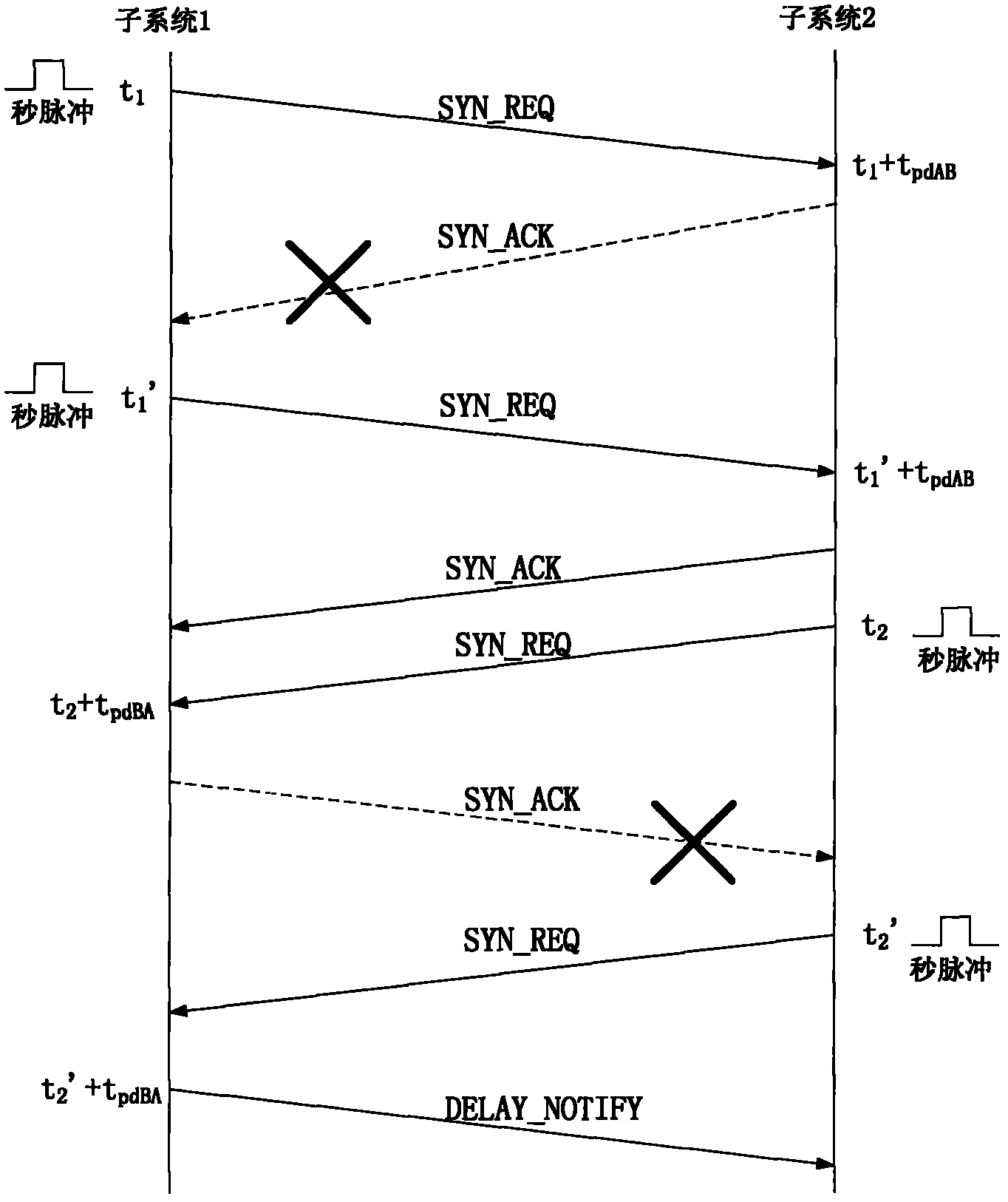
The invention relates to a method for acquiring accurate line transmission delay during time synchronization. The method comprises the following steps: a subsystem is selected as a main subsystem; an auxiliary subsystem is selected; the main subsystem sends a pulse per second at t1 time, and the pulse per second reaches the auxiliary subsystem after line transmission delay tpdBA; after the auxiliary subsystem receives the pulse per second, the auxiliary subsystem starts a timing register; the auxiliary subsystem computes that the time of the auxiliary subsystem is delayed for tpdAB compared with the main subsystem by combining with a counting time value Delta t' from a current time value; the auxiliary subsystem sends the pulse per second to the main subsystem at t2 time, and when the pulse per second reaches the main subsystem after the line transmission delay tpdBA, the time value t3 of the main subsystem is recorded at the time; and the one-way delay tpd of the main subsystem and the auxiliary subsystem is computed through tpd=(tpdBA+tpdAB) / 2=(t3-t2). According to the method disclosed by the invention, the one-way or two-way accurate line transmission delay of a system can be accurately obtained, and therefore delay is convenient to subsequentially compensate.

Description

technical field [0001] The invention relates to the field of data communication, in particular to a method for obtaining accurate line transmission delay in time synchronization. Background technique [0002] In the communication field, the GPS (Global Positioning System, Global Positioning System) scheme is used for time synchronization of traditional 2G networks, which has high cost, difficult maintenance and potential safety hazards. With the development of packet switching technology, packet switching technology is becoming more and more mature, replacing TDM (Time Division Multiplex) technology more and more, and is widely used in the access layer, aggregation layer and core layer of the communication network. The normal operation of many telecommunications services still requires the characteristics of traditional TDM telecommunications networks, especially for 3G / 4G wireless communication IP radio frequency access networks, requiring communication equipment to meet pr...

Claims


Application Information

Patent Timeline
Patent Type & Authority Applications(China)
IPC IPC(8): H04L7/00
Inventor 赵咸红
Owner FENGHUO COMM SCI & TECH CO LTD
Learn More