

A Microwave Digital Image Transmission System
A transmission system and digital image technology, applied in the field of microwave digital image transmission system, can solve the problems of limited number of frequency points, lack of data transmission, confidentiality, reliability, and maintainability that cannot satisfy users, so as to save antennas Use quantity, reduce system cost, improve rapid deployment and maintainability
- Summary
- Abstract
- Description
- Claims
- Application Information
AI Technical Summary
Problems solved by technology
Method used
Image

Examples
Embodiment 1
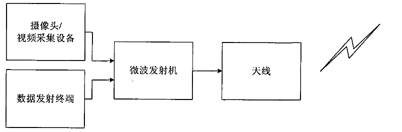
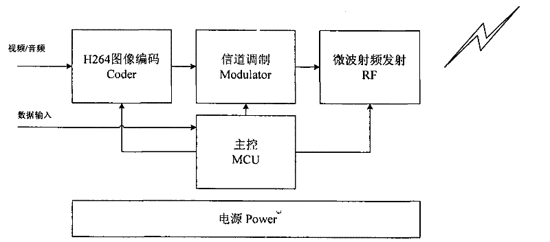
[0030] Example 1: Transmitter
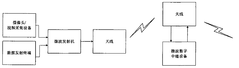
[0031] Considering the propagation characteristics of the microwave system in the wireless channel, and the propagation path between the transmitter and the receiver may be the line of sight between two points, and there may be obstacles such as mountains and buildings. Therefore, the transmitter is divided into multiple situations during deployment. First, the basic transmitter unit composed of an acquisition camera (head), a microwave transmitter, and a transmitter antenna can be deployed in a high-altitude and short-distance environment (transmitter A); When there are obstacles such as mountains, highlands, and buildings, a relay device (transmitter B) is added between the basic transmitting unit and the receiving end (such as the top of the mountain highland, the top of the building) to complete the forwarding of image information; finally, If it is necessary to transmit data, a data transmitting terminal can be added on the basis of the bas...
Embodiment 2
[0039] Example 2: Receiver
[0040] According to the requirements of the use environment, the receiving end selects a single-channel receiving device (receiving end A) under the limited site and single transmission requirements, and directly uses the monitor to complete the reproduction of the transmitting end information; when multi-point transmission and multi-scenario monitoring are required, select multiple The receiving device (receiving terminal B) uses a monitor to reproduce the information of multiple transmitting terminals.
[0041] Receiver A form
[0042] Such as Figure 5 As shown, when required for general use, it is used with a single transmitter, using Form A, including image monitor, computer, single-channel microwave receiver and antenna. The antenna receives the electromagnetic wave signal and sends it to the single-channel microwave receiver. The single-channel microwave receiver restores the useful signal to the real-time video image information or data inf...
Embodiment 3
[0050] Embodiment 3: network server side
[0051] Since the microwave digital image transmission system transmits space through electromagnetic waves, it has certain advantages in emergency communication, rapid deployment, and mobility flexibility, but is subject to certain constraints in communication distance. In order to meet the requirements of remote access, use, and command The function is added to the network server side, and the existing public information network such as the Internet, 3G network and other wired networks are used to improve the application range of the system.
[0052] Such as Figure 11 As shown, it is also possible to add a network server at the back end of the microwave receiver, such as computer terminal / server, 3G network terminal and other equipment. Connect the Ethernet interface of the microwave receiver to the computer terminal or server connected to the Internet, and through IP, the remote computer on the Internet can access the microwave re...
PUM
 Abstract
Description
Claims
Application Information