
A method for through-hole reflow soldering

A reflow soldering and reflow soldering technology, which is applied in the direction of assembling printed circuits with electrical components, can solve the problems of thermal damage of plug-in components, insufficient tin penetration in holes, and insufficient tin penetration, so as to improve reliability and soldering quality and high reliability, simple and convenient operation

Active Publication Date: 2011-12-21
南通卓效自动化有限公司
View PDF5 Cites 16 Cited by
  • Summary
  • Abstract
  • Description
  • Claims
  • Application Information

AI Technical Summary

Problems solved by technology

[0003] This method has the following disadvantages: 1. During manual repair soldering, it often occurs that the temperature of the soldering iron for manual soldering is high (about 380 ° C), causing thermal damage to plug-in components; 2. The layout of the PCB board may lack space for manual repair soldering; 3. .Plug-in components do not come out of the pins or the pins are not enough, which cannot meet the requirements for the height of tin climbing and may easily cause defects such as cold soldering and virtual soldering; The welding quality of the feet is poor, and the welding strength cannot meet the requirements; 5. Manual repair welding has low efficiency and poor reliability; 6. When manual repair welding cannot be welded, re-selection is often required, which affects the realization of product functions

Method used


Image

  • A method for through-hole reflow soldering
  • A method for through-hole reflow soldering
  • A method for through-hole reflow soldering

Examples


Embodiment Construction

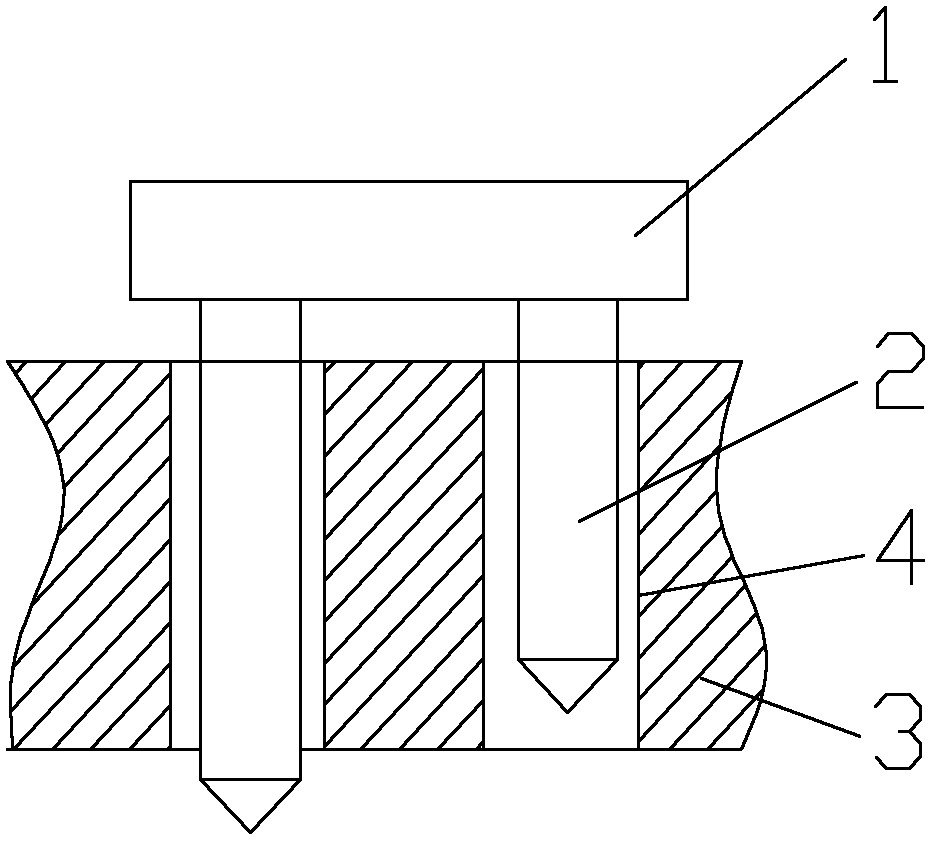
[0018] The PCB board 3 is provided with an HDMI plug-in component 1 which is a patch connector with four pins 2. Among them, the length of pin 2 is 1.8 mm and 2.2 mm, and the thickness of PCB board 3 is 2.0 mm. After inserting this plug-in component 1 into the corresponding plug-in hole 4 on PCB board 3, pin 2 with a length of 1.8 mm is not The pin 2 with a length of 2.2 mm has a pin 2 of 0.2 mm, which does not meet the pin requirement of 0.8 mm to 1.5 mm, such as figure 1 Shown.

[0019] When using traditional methods, namely wave soldering and manual repair soldering, the front side cannot penetrate the tin, and the amount of solder filling in the plug-in hole 4 does not meet the 75% filling requirement of the plug-in hole 4 of IPC610D (Electronic Industry Solder Joint Inspection Standard). The reliability of the component is poor. At the same time, the plug-in hole 4 places tin piles, the surrounding large copper skin absorbs heat, and the solder joints are easy to cause cold ...


PUM


Abstract

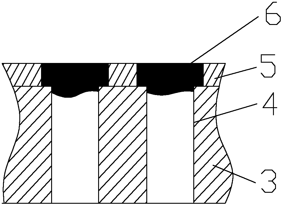
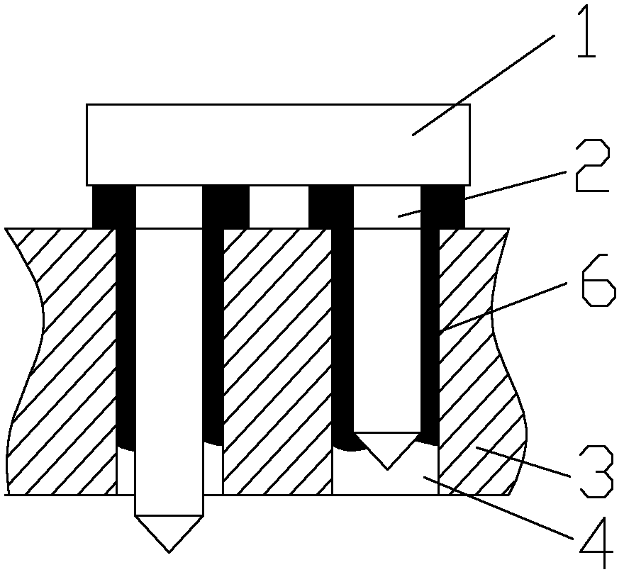
The invention relates to a through-hole reflow soldering method. The method is characterized by printing solder at the plug-in hole positions where exposed pins can not meet the wave soldering requirement on a PCB (printed circuit board), inserting pins of a corresponding plug-in component into plug-in holes, the pins bringing part of solder paste in the plug-in hole walls and then carrying out reflow soldering. The method has the following advantages: temperature damage to the plug-in component is not easy to cause, the lack of space for manual repair soldering during manual repair solderingis avoided, cold soldering, poor soldering and other soldering defects are not easy to cause, the soldering quality is good, the reliability is high, and the soldering efficiency is high, and the method is suitable for soldering of the plug-in components with the exposed pins failing to meet the wave soldering requirement.

Description

Technical field [0001] The invention relates to a soldering method of plug-in components, in particular to a method for reflow soldering the through-holes of plug-in components on the PCB board when the size of the plug-in component pins does not match the thickness of the PCB board. Background technique [0002] Components, is the general term for components and devices. Existing plug-in components are usually welded by wave soldering. In order to achieve a good wave soldering effect, there are relatively strict requirements on the lead length of the plug-in components. The pin length refers to the size of the pin of the plug-in component that exceeds the reverse surface of the PCB after being inserted into the PCB board, and the pin length of about 0.8 mm to 1.5 mm must be met. When the lead length of the plug-in component does not meet the requirements, that is, less than 0.8 mm or no lead at all, manual repair welding is often used to weld the plug-in component. [0003] This...

Claims


Application Information

Patent Timeline
IPC IPC(8): H05K3/34
Inventor 董萌刘海龙赖增茀黄海兵
Owner 南通卓效自动化有限公司
Learn More