
Alternating regenerative furnace and process of operating same

A regenerative, kiln technology, used in combustion methods, glass furnace equipment, lighting and heating equipment, etc., can solve problems such as reduced kiln productivity, and achieve the effect of eliminating the effects of heat generation and heat transfer.

Inactive Publication Date: 2014-04-16
LAIR LIQUIDE SA POUR LETUDE & LEXPLOITATION DES PROCEDES GEORGES CLAUDE
View PDF4 Cites 0 Cited by
  • Summary
  • Abstract
  • Description
  • Claims
  • Application Information

AI Technical Summary

Problems solved by technology

[0017] The problem with known regenerative kilns is that immediately after the reversal of the operation of the regenerator there is practically no combustion oxidant supplied from the regenerator to the regenerator
Thus during said transitional state of each reversing of the operation of the regenerator the heat generation in the combustion chamber is reduced or even interrupted with a corresponding reduction in the productivity of the kiln

Method used


Image

  • Alternating regenerative furnace and process of operating same
  • Alternating regenerative furnace and process of operating same
  • Alternating regenerative furnace and process of operating same

Examples


no. 2 example

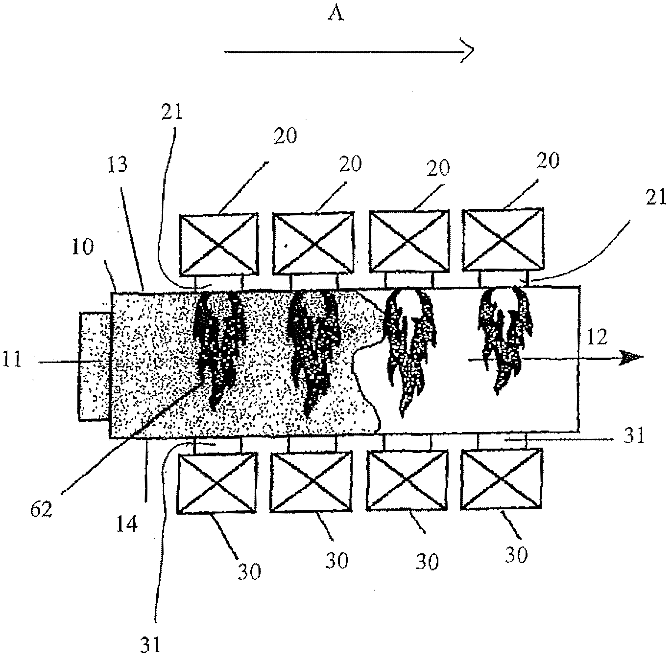
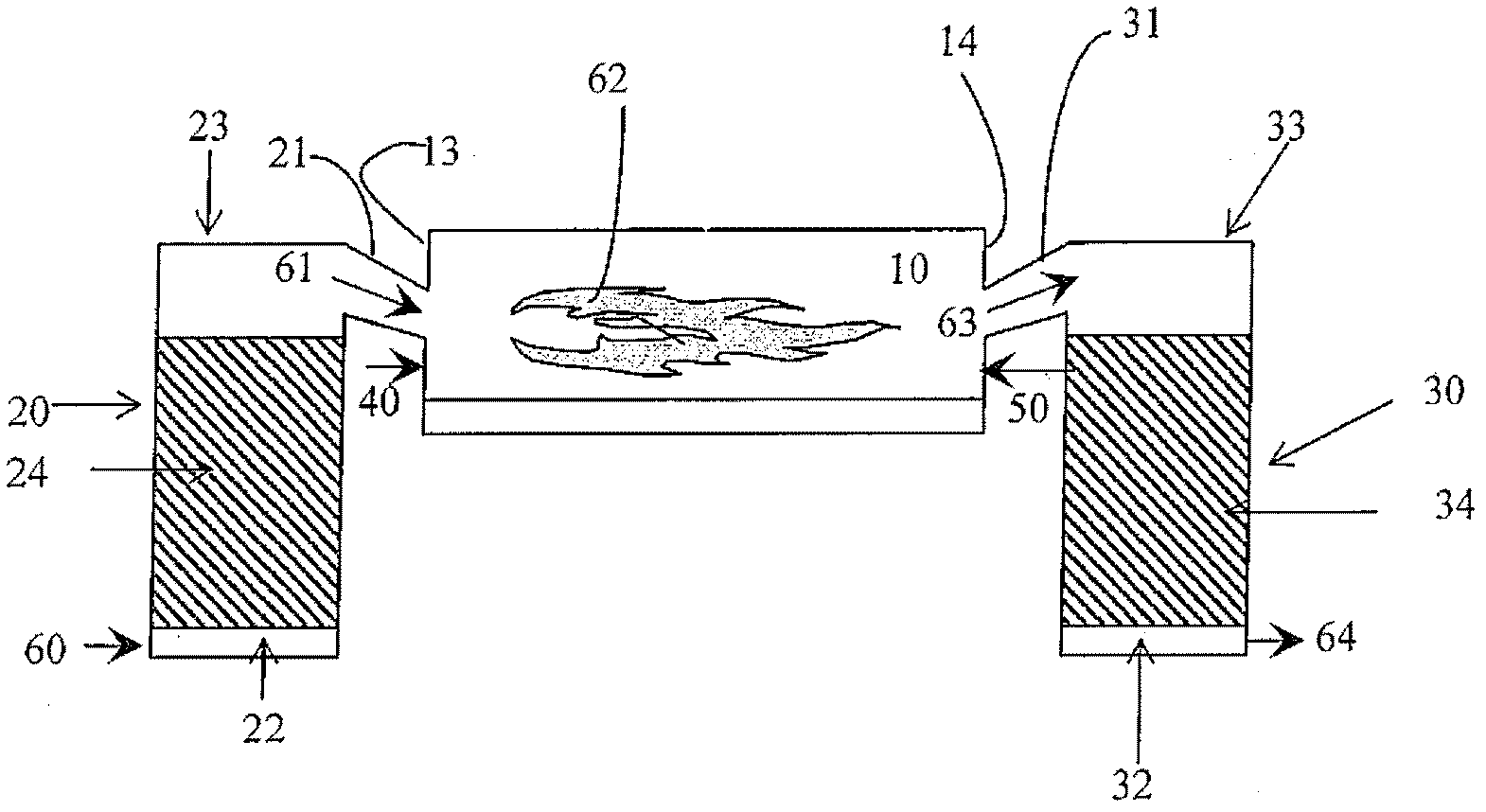
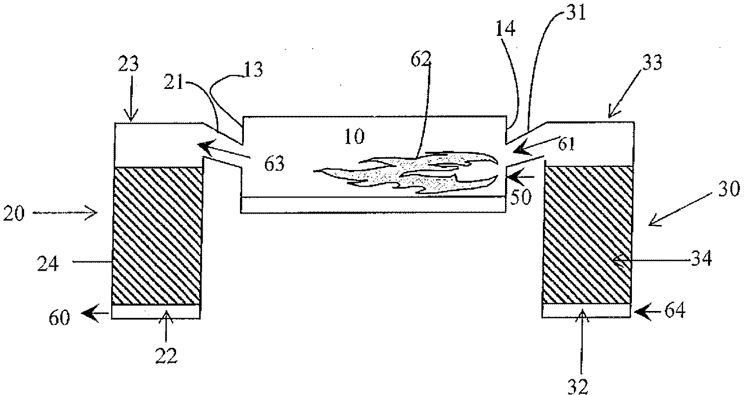
[0110] In an alternative embodiment of the method of the present invention, the final stage of the first state is as in the prior art embodiment (see figure 2 ) so that the regenerators of the regenerator group in heat recovery mode are filled with flue gas at the end of the first state.

[0111] According to a second embodiment, during the transition period of about 50 seconds immediately following the state reversal, oxygen-containing gas 66 is injected into the top end of one or more regenerators that were in heat recovery mode prior to the state reversal (or alternatively optionally injected into the regenerator port 31). exist figure 2 and 7 In the case shown, these are the second set of regenerators 30 .

[0112] Thus the oxygen-containing gas 66 injected into the tips of the regenerators 30 (or alternatively into the regenerator ports 31) during the transition period is not equal to the amount of gas leaving the second set of regenerators 30 during the transition p...


PUM


Abstract

Alternating regenerative furnace and process of operating an alternating regenerative furnace, in which during the transition phase in which the respective regenerators (20,30) switch between heat-recovery mode and pre-heating mode and vice-versa, the regenerator or regenerators (20,30) which before the transition phase were in heat-recovery mode inject a mixture of flue gas and oxygen-containing gas into the combustion chamber (10) of the furnace, which mixture combusts with fuel injected into the combustion chamber (10) to produce heat.

Description

technical field [0001] The present invention relates to an improved method of operating a regenerative kiln and a regenerative kiln suitable for said method. Background technique [0002] In the operation of a kiln, heat balance is very important. Many methods, installations and devices have been developed, inter alia, to improve the kiln thermal balance by recovering heat from the flue gases leaving the combustion chamber of the kiln. [0003] An example of such a facility for improving the heat balance of a kiln is the regenerative kiln, which is widely used in industry, especially in the case of continuously operating kilns. [0004] Regenerative kilns are equipped with a number of regenerators, each of which is connected via its regenerator port to the combustion chamber of the kiln. The regenerator operates alternately as (1) a heat recovery device for recovering heat from the flue gases leaving the combustion chamber of the kiln and as (2) a pre-heater for pre-heatin...

Claims


Application Information

Patent Timeline
Patent Type & Authority Patents(China)
IPC IPC(8): C03B5/237F23L7/00F23L15/02
CPCY02E20/344F23L15/02Y02E20/322C03B5/237F23L7/007C03B5/235Y02P40/57Y02E20/32Y02E20/34Y02P40/50
Inventor P·祖凯利
Owner LAIR LIQUIDE SA POUR LETUDE & LEXPLOITATION DES PROCEDES GEORGES CLAUDE
Learn More