Eureka AIR delivers breakthrough ideas for toughest innovation challenges, trusted by R&D personnel around the world.
Magnetic powder vacuum mixer
What is Al technical title?
Al technical title is built by PatSnap Al team. It summarizes the technical point description of the patent document.
A vacuum mixing and agitator technology, applied in mixers, mixer accessories, mixers with rotary mixing devices, etc., can solve problems such as waste, increase production costs, environmental pollution, etc., achieve uniform distribution of binders, and save production costs. , the effect of reducing production costs
Active Publication Date: 2013-06-12
潍坊德诺磁业有限公司
View PDF4 Cites 0 Cited by
Summary
Abstract
Description
Claims
Application Information
AI Technical Summary
This helps you quickly interpret patents by identifying the three key elements:
Problems solved by technology
Method used
Benefits of technology
Problems solved by technology
The traditional magnetic powder mixing mixer is to mix the raw material rare earth permanent magnet powder and epoxy resin binder under the protection of nitrogen, which has the following defects: 1. During mass production, the quality of the product will vary; 2. In order to To prevent the rare earth permanent magnet powder from being oxidized during the stirring process, it is necessary to use nitrogen protection, which is expensive and increases the production cost; 3. During the mixing process, a large amount of acetone gas volatilized by acetone as a solvent cannot be effectively recovered, which not only produces waste, It will also pollute the environment and cause great harm to the personal health of the staff.
Method used
Image
Click on the blue label to locate the original text in one second.
Reading with bidirectional positioning of images and text.
Examples
Embodiment
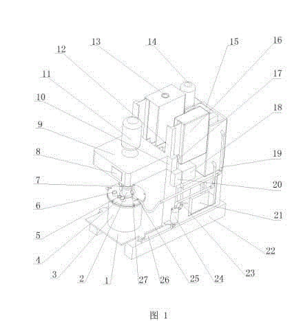
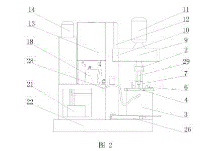
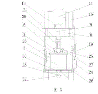
[0027] A magnetic powder vacuum mixing mixer, such as Figure 1-Figure 5 As shown, it includes a frame 22 and a mixing device, a hydraulic drive device, a condensate recovery system, a heating device and an electric control device arranged on the frame 22 .
[0028] The mixing device comprises a feed bin 3 installed on the frame 22, an elevating table 9 arranged on the top of the elevating table 3, a main motor 11 installed on the top surface of the elevating table 9, a transmission shaft 29 connected with the main motor 11 transmission, A stirring mechanism 31 connected to the lower end of the transmission shaft 29, a bin cover 4 arranged on the bin 3, and a discharge port 30 arranged at the bottom of the bin 3. The power transmission shaft 29 vertically runs through the lifting platform 9 and the silo cover 4 . Drive shaft 29 periphery is provided with connector 2, and the upper end of connector 2 is connected with lifting platform 9 bottom surfaces, and the lower end of co...
PUM
Abstract
The invention discloses a magnetic powder vacuum mixer. The mixer comprises a frame, a mixing device, a hydraulic driving device, a condensation recovering device, a heating device and an electric controlling device. The mixing device comprises a material chamber, a lifting platform, a main motor, a transmission shaft, a stirring mechanism, a material chamber cap and a discharging port. The hydraulic driving device comprises a hydraulic oil pump, a sliding plate, a horizontal hydraulic cylinder, a slideway, a sliding sleeve and a lifting hydraulic cylinder. The condensation recovering device comprises a condensing machine set, a vacuum pump, a vacuum valve, a recovering tank and pipelines. The heating device comprises a heater, a heat circulating pump and a heat conducting water pipe. Theelectric controlling device comprises an electric controlling box and a frequency converter. The material chamber cap is provided with a gas discharging valve, two through holes and a camera hole. A display screen is arranged on one side of the lifting platform. With the mixer provided by the invention, magnetic powder can be prevented from being oxidized during a mixing procedure, the cost of nitrogen protection can be saved, and the product quality can be ensured. With the condensation recovering device, acetone can be recovered and reused, such that the production cost is saved, and the production process is green and environment-friendly.
Description
technical field [0001] The invention relates to a material mixing device used in a bonded magnet compression molding process, in particular to a magnetic powder vacuum mixing agitator. Background technique [0002] As a special equipment for bonded NdFeB permanent magnets, the magnetic powder mixing mixer is applied to the mixing procedure in the bonded magnet compression molding process. The traditional magnetic powder mixing mixer is to mix the raw material rare earth permanent magnet powder and epoxy resin binder under the protection of nitrogen, which has the following defects: 1. During mass production, the quality of the product will vary; 2. In order to To prevent the rare earth permanent magnet powder from being oxidized during the stirring process, it is necessary to use nitrogen protection, which is expensive and increases the production cost; 3. During the mixing process, a large amount of acetone gas volatilized by acetone as a solvent cannot be effectively recov...
Claims
Application Information
Patent Timeline
Application Date:The date an application was filed.
Publication Date:The date a patent or application was officially published.
First Publication Date:The earliest publication date of a patent with the same application number.
Issue Date:Publication date of the patent grant document.
PCT Entry Date:The Entry date of PCT National Phase.
Estimated Expiry Date:The statutory expiry date of a patent right according to the Patent Law, and it is the longest term of protection that the patent right can achieve without the termination of the patent right due to other reasons(Term extension factor has been taken into account ).
Invalid Date:Actual expiry date is based on effective date or publication date of legal transaction data of invalid patent.