Al technical title is built by PatSnap Al team. It summarizes the technical point description of the patent document.
A feeder and automatic technology, which is applied in the direction of shearing device, pipe shearing device, and accessories of shearing machines, etc., can solve the problems of difficult clamping of pipes, heavy load of driving motor, and existence of danger, etc., to eliminate potential risks and reduce Requirements, the effect of improving the efficiency of use
Inactive Publication Date: 2011-12-28
莱州市山普管件制造有限公司
View PDF6 Cites 17 Cited by
Summary
Abstract
Description
Claims
Application Information
AI Technical Summary
This helps you quickly interpret patents by identifying the three key elements:
Problems solved by technology
Method used
Benefits of technology
Problems solved by technology
[0007] The purpose of the present invention is to provide an automatic rotary cutting machine to solve the technical problems that the operator is exposed to the working surface during rotary cutting of pipes, there is danger, the load of the driving motor is large, and the pipes are not easy to clamp
Method used
Image
Click on the blue label to locate the original text in one second.
Reading with bidirectional positioning of images and text.
Examples
Embodiment Construction
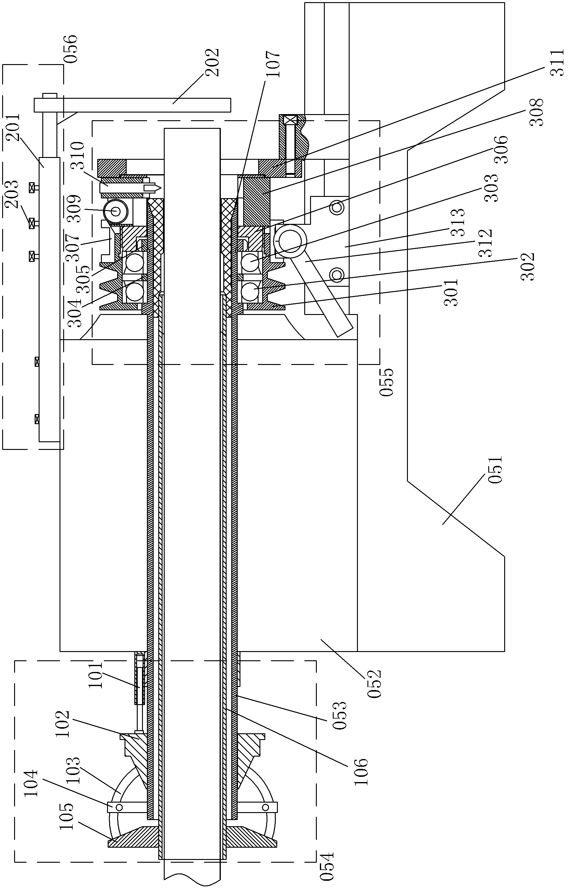
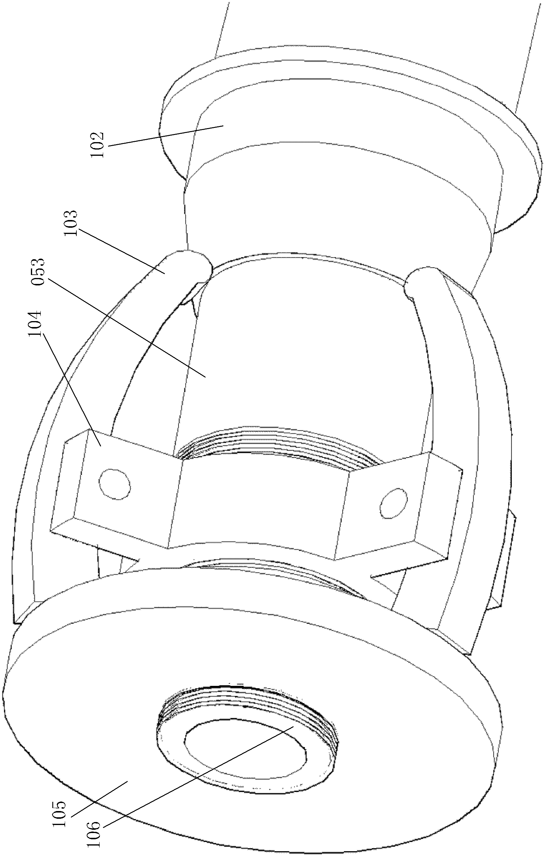
[0020] Such as Figure 1 to Figure 3 As shown, this embodiment includes a control circuit, a driving motor, a machine tool 051, an equipment fixing frame 052, a hollow spindle 053, a clamping device 054, a rotary cutting device 055 and a positioning device 056, and the equipment fixing frame 052 is fixedly installed on the machine tool 051. The hollow main shaft 053 runs through the left and right sides of the equipment fixing frame 052 from left to right and is fixedly connected on the equipment fixing bracket 052. The inner diameter of the hollow main shaft 053 gradually increases near the right end surface, forming a conical cavity. An annular protrusion 053a is provided on the outer wall near the right end of the hollow main shaft 053, and its cross-sectional shape is rectangular. The clamping device 054 is installed on the left end of the hollow main shaft 053, the rotary cutting device 055 is installed on the right end of the hollow main shaft 053, the positioning device...
PUM
Abstract
The invention discloses an automatic rotary cutting blanking machine, and relates to a processing machine for cutting pipes. The automatic rotary cutting blanking machine comprises a control circuit, a drive motor, a machine tool, an equipment fixing frame, a hollow main shaft, a clamping device, a rotary cutting device and a positioning device. The clamping device comprises a clamping cylinder, a gradient sliding bush, a jaw, a jaw fixing ring, a tensioning disc, a chuck pull pipe and a chuck. The positioning device comprises an adjusting sleeve, a limiting vertical plate and a positioning bolt. The rotary cutting device comprises a belt pulley, a first bearing, a second bearing, a bushing ring, a circular nut, a cutter body cover, a cutter pressing body, a guide block, a cutter clamping body, a cutter bar, a front baffle plate, a shifting fork handle and a shifting fork bracket. By using the blanking machine, the pipes are not rotationally cut; and by adopting the rotating mode of the cutter, the load of the drive motor is reduced, the clamping requirement of the pipes is reduced, and the structure of the pipe clamping device is simplified.
Description
technical field [0001] The invention relates to a mechanical processing device, in particular to a processing machine for cutting pipes. Background technique [0002] Most of the existing pipe cutting equipment uses circular saws to cut pipes, and also uses turning tools for cutting. During the cutting process, the reverse rotation of pipes and cutters is used to speed up the cutting process. [0003] The use of circular saws has restrictions on the wall thickness and diameter of the pipe. At the same time, the smoothness of the processed part section is poor, and there are burrs. Secondary grinding is required, which prolongs the processing cycle, so it is gradually eliminated. [0004] Using the turning tool for processing can make the section of the part smooth and the machining accuracy is high. According to the shape of the cutting edge of the turning tool, the section of the part can also be processed into a plane or a slope at any angle. [0005] During the cutting p...
Claims
Application Information
Patent Timeline
Application Date:The date an application was filed.
Publication Date:The date a patent or application was officially published.
First Publication Date:The earliest publication date of a patent with the same application number.
Issue Date:Publication date of the patent grant document.
PCT Entry Date:The Entry date of PCT National Phase.
Estimated Expiry Date:The statutory expiry date of a patent right according to the Patent Law, and it is the longest term of protection that the patent right can achieve without the termination of the patent right due to other reasons(Term extension factor has been taken into account ).
Invalid Date:Actual expiry date is based on effective date or publication date of legal transaction data of invalid patent.