Non-contact pantograph-catenary arc detection system

A non-contact, detection system technology, applied in the direction of vehicle route interaction equipment, railway car body parts, railway signal and safety, etc. Stream quality and other issues, to achieve the effect of function expansion and maintenance convenience, strong equipment reliability, high detection accuracy and reliability

Inactive Publication Date: 2011-12-28
CHENGDU TANGYUAN ELECTRICAL APPLIANCE
View PDF3 Cites 12 Cited by
  • Summary
  • Abstract
  • Description
  • Claims
  • Application Information

AI Technical Summary

Problems solved by technology

[0013] In electrified railways, the phenomenon of pantograph-catenary arcing will occur due to various factors, which will cause great damage to the pantograph and contact wire, affect the quality of the pantograph-catenary current, and will generate overvoltage, affecting electrification quality of the railway
At this stage, there is no specific equipment for the detection of pantograph-catenary arcing phenomenon, mainly due to the existence of many uncertain factors such as the randomness and instantaneousness of pantograph-catenary arcing

Method used


Image

  • Non-contact pantograph-catenary arc detection system
  • Non-contact pantograph-catenary arc detection system

Examples


Embodiment

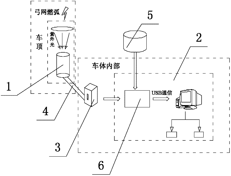
[0025] Such as figure 1 As shown, a non-contact pantograph-catenary arc detection system includes an optical imaging measurement device 1, an ultraviolet photoelectric sensing device and a data analysis and processing system 2. The optical imaging measurement device 1 collects optical signals of pantograph-catenary arcing, and the ultraviolet photoelectric The sensing device converts the optical signal into a pulsed current signal, and the data analysis and processing system 2 analyzes the pulsed current signal into the duration and intensity of arcing and the number of arcing occurrences for each span, and at the same time combines the information in the existing database, Precise location of the area where arcing occurs. The optical imaging measuring device 1 is an ultraviolet collection lens group capable of amplifying the light signal of arc burning several tens of times, and the ultraviolet collection lens group is installed outside the roof of the train. The ultraviolet...


PUM


Abstract

The invention discloses a non-contact pantograph-catenary arc detection system, which includes an optical imaging measurement device, an ultraviolet photoelectric sensing device and a data analysis and processing system. The device converts the optical signal into a pulsed current signal, and the data analysis and processing system analyzes the pulsed current signal into the duration and intensity of arcing and the number of arcing occurrences for each span. The area of ​​the arc is precisely positioned. The invention applies the principle of ultraviolet photoelectric detection to pantograph-catenary arc detection technology for the first time, and uses the specific wavelength emitted by pantograph-catenary arc as its detection feature. By detecting the ultraviolet light emitted when pantograph-catenary arcing occurs, it is judged whether there is pantograph-catenary arcing, and parameters such as arcing time and intensity are calculated according to the corresponding algorithm, and the arcing site is checked through the existing database Positioning is convenient for future line maintenance and transformation.

Description

technical field [0001] The invention relates to a non-contact pantograph-catenary arc detection system. Background technique [0002] In the electrified railway, the operation of the electric locomotive needs to obtain electric energy through the contact between the pantograph on its top and the contact wire. The contact state between the pantograph and the catenary line directly affects the current quality of the locomotive, and it is also a comprehensive reflection of the geometric eigenvalues ​​of the catenary. The hard point or uneven wear of the contact line in the actual working condition will directly lead to poor pantograph-catenary contact, resulting in arcing and the following situations: (1) causing unstable operation of the electric locomotive; (2) causing abnormalities between pantograph-catenary (3) produce electromagnetic interference; (4) deteriorate the rectification condition of the traction motor; (5) cause overvoltage in the main circuit. Therefore, it ...

Claims


Application Information

Patent Timeline
Patent Type & Authority Applications(China)
IPC IPC(8): B61L1/20
Inventor 于龙李昌峻赵文军金光张士奎杨佳
Owner CHENGDU TANGYUAN ELECTRICAL APPLIANCE
Why Eureka
Try Eureka