
A device and method for MBR membrane fouling control

A membrane fouling and sewage technology, applied in chemical instruments and methods, water/sewage multi-stage treatment, water/sludge/sewage treatment, etc. The effect of avoiding membrane fouling, improving resistance to hydraulic shock loads and reducing operating costs

Inactive Publication Date: 2011-12-28
BEIJING DRAINAGE GRP CO LTD
View PDF1 Cites 10 Cited by
  • Summary
  • Abstract
  • Description
  • Claims
  • Application Information

AI Technical Summary

Problems solved by technology

These methods can alleviate membrane fouling to a certain extent, but there are problems such as high energy consumption, increased chemical consumption, and high operating costs. At the same time, chemical agents also introduce secondary pollution into the system.

Method used


Image

  • A device and method for MBR membrane fouling control
  • A device and method for MBR membrane fouling control

Examples


Embodiment 1

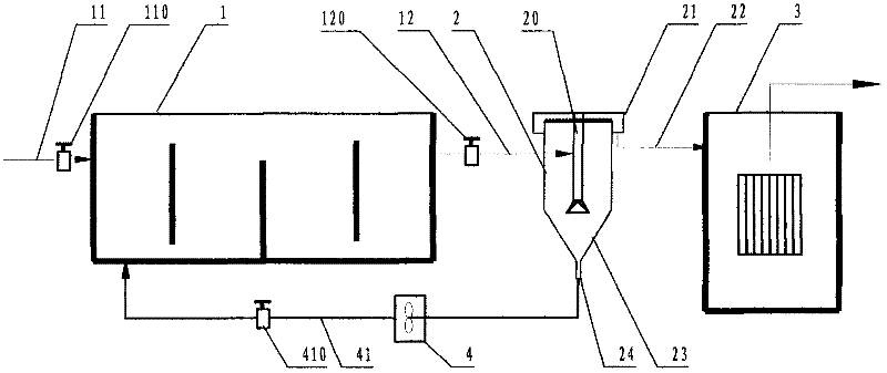
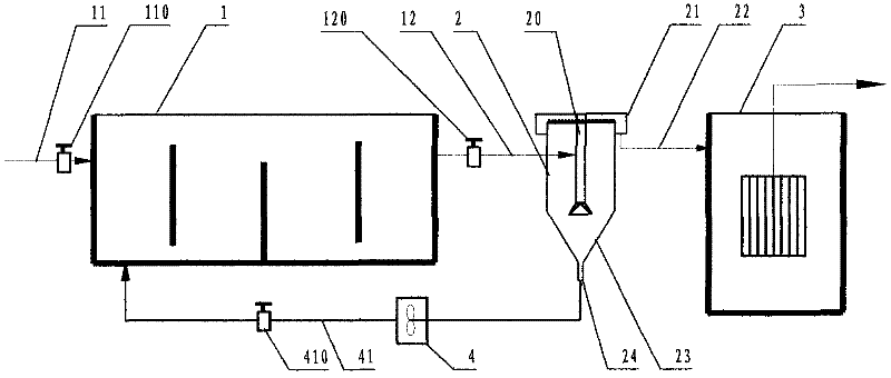
[0022] Embodiment 1: a kind of device that uses the MBR membrane pollution control of following method, be provided with biological treatment unit 1 and submerged membrane treatment unit 3, described biological treatment unit is made of anaerobic pond, anoxic pond and aerobic pond , it is characterized in that: a quick sedimentation tank 2 is arranged between the biological treatment unit and the membrane treatment unit, the quick sedimentation tank is a cylindrical tank wall, the bottom 23 is funnel-shaped, and the funnel-shaped bottom is provided with a mud collecting tank Groove 24, this mud collecting tank communicates with the anaerobic tank front end of described biological treatment unit through a sludge return device 4 that is provided with submerged propeller or air lift device; Cylinder 20, this settling cylinder is communicated with the water outlet of described biological treatment unit through water inlet pipe, is provided with overflow weir 21 at the upper mouth o...

Embodiment 2

[0023] Example 2: A device for MBR membrane pollution control consists of a biological treatment unit, a rapid sedimentation tank, and a membrane tank. Sewage first enters the biological treatment unit, the sludge concentration in the biological treatment unit is about 7000mg / L, and the hydraulic retention time is 6h. The effluent of the biological unit enters the fast sedimentation tank connected to it. The sedimentation time of the fast sedimentation tank is 20 minutes. The activated sludge with good sedimentation performance settles rapidly in the rapid sedimentation tank, and the activated sludge with poor sedimentation performance enters the membrane reaction with the effluent from the overflow weir. appliance pool. The reactor is cleaned every 3 weeks, and it has been operated for 3 months without maintenance. The membrane flux has always been maintained at 18L / m 2 h, the occurrence of membrane fouling is effectively controlled.


PUM


Abstract

The invention relates to a device for MBR membrane pollution control, which is provided with a biological treatment unit and a submerged membrane treatment unit. The biological treatment unit is composed of anaerobic pool, anoxic pool and aerobic pool. There is a quick sedimentation tank between them. The control method is: 1) The sewage first enters the biological treatment unit; 2) The effluent of the biological unit enters the fast sedimentation tank connected to it; 3) The rapid separation of mud and water is realized in the fast sedimentation tank, and during the operation, according to the rapid sedimentation tank The hydraulic retention time, the sludge concentration of the biological treatment unit, and the requirements for nitrogen and phosphorus removal adjust the sludge reflux ratio of the rapid sedimentation tank; 4) Membrane cleaning is performed every 1 to 4 weeks according to the membrane fouling situation; 5) Every 1 to 4 weeks, the membrane is cleaned; At 4 weeks, during the membrane cleaning period, the membrane tank was drained and the mix was drained. The invention is suitable for the new construction or reconstruction of the submerged MBR process, can reduce the sludge concentration of the membrane tank, ensure the high sludge concentration of the biological treatment unit, prolong the cycle of membrane cleaning, occupy less land, have high efficiency and good effect.

Description

technical field [0001] The invention relates to a sewage treatment device and method, in particular to a highly efficient and economical MBR membrane pollution control device and method. The device and method can effectively alleviate the occurrence of MBR membrane pollution, prolong the cycle of membrane cleaning, and improve the membrane flow rate. Quantity, reduce the cost of membrane cleaning, suitable for the submerged MBR process field of domestic sewage or industrial wastewater treatment. Background technique [0002] my country's per capita fresh water resources are only 1 / 4 of the world's average level, and it is one of the countries with the poorest per capita water resources in the world. With the rapid development of my country's economy, the consumption of water resources has doubled. On the one hand, it has caused a shortage of water resources and increased the generation of sewage. The national sewage discharge has increased from 31.5 billion tons in 1980 to 2...

Claims


Application Information

Patent Timeline
IPC IPC(8): C02F9/14C02F3/30C02F1/52
Inventor 杨岸明甘一萍常江张树军彭永臻刘立超孟春霖刘秀红赵颖
Owner BEIJING DRAINAGE GRP CO LTD
Learn More