
A fan control circuit for prolonging the life of fan DC carbon brush motor

A fan motor and fan control technology, applied in pump control, emergency protection circuit devices, electrical components, etc., can solve the problems of accelerated wear of the motor working current carbon brush, arcing, carbon deposition in the commutator slot, etc., to eliminate the motor Unstable working phenomenon, eliminating the effect of increasing the working current of the motor and prolonging the life of the fan

Active Publication Date: 2011-12-28
KENNEDE ELECTRIONICS MFG CO LTD
View PDF7 Cites 6 Cited by
  • Summary
  • Abstract
  • Description
  • Claims
  • Application Information

AI Technical Summary

Problems solved by technology

[0006] The working current of the motor becomes larger → the "arcing" phenomenon between the carbon brush and the commutator becomes serious → the wear of the carbon brush accelerates → carbon deposits in the commutator slot → the working current of the motor becomes larger
[0007] 3. The starting current of the DC carbon brush motor is 7-8 times the normal working current. In the starting phase, due to the large starting current, the phenomenon of "arcing" between the carbon brush and the commutation is very serious, and the carbon brush is worn during the starting phase. Very serious, very serious impact on life expectancy

Method used


Image

  • A fan control circuit for prolonging the life of fan DC carbon brush motor
  • A fan control circuit for prolonging the life of fan DC carbon brush motor
  • A fan control circuit for prolonging the life of fan DC carbon brush motor

Examples


Embodiment Construction

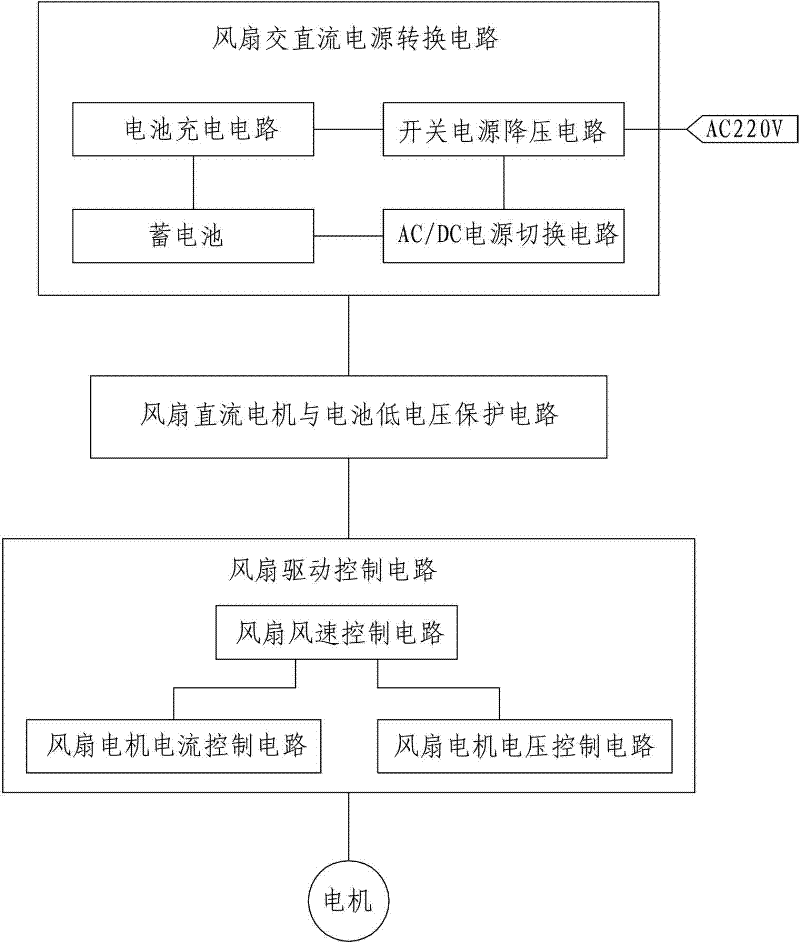
[0024] see figure 1 and Figure 5 , The invention discloses a fan control circuit for prolonging the service life of a fan DC carbon brush motor, which includes three major circuits including a fan AC-DC power conversion circuit, a fan DC motor and battery low-voltage protection circuit, and a fan drive control circuit.

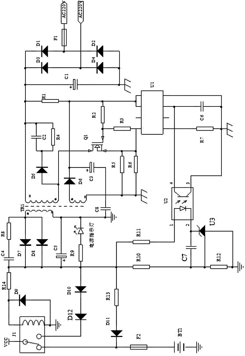
[0025] Among them, the fan AC-DC power conversion circuit can realize two kinds of power supply: industrial frequency AC power supply and DC power supply (rechargeable battery). The circuit schematic diagram is as follows: figure 2 shown. This circuit is divided into three parts: the first is the switching power supply step-down circuit, which consists of D1, D2, D3, D4, D5, D6, D7, D8, D9, R1, R2, R3, R4, R5, R6, R7, R8, R9 , R10, R11, R12, Q1, TR1, U1, U2, U3, C1, C2, C3, C4, C5, C6, C7, C8, F1 form a switching power supply step-down circuit, which converts the mains power into a DC carbon brush motor The required low-voltage direct current, in which U1...


PUM


Abstract

The invention discloses a fan control circuit for prolonging the service life of a direct current carbon brush motor of a fan, which comprises an alternating and direct current power supply conversion circuit of the fan, a direct current motor of the fan, a battery low-voltage protective circuit and a driving control circuit of the fan; wherein the alternating and direct current power supply conversion circuit of the fan comprises a rechargeable storage battery, a switch power voltage reduction circuit, a battery charging circuit and an alternating current / direct current (AC / DC) power supply switching circuit; and the driving control circuit of the fan comprises an air speed control circuit of the fan, a motor current control circuit of the fan and a motor voltage control circuit of the fan. The fan control circuit can prevent the motor and the battery form being harmed due to too low power voltage, can stabilize the working current of the direct current carbon brush motor of the fan at a rated working current value, simultaneously controls the voltage at the lower limit of the rated working voltage of the motor and eliminates the phenomenon that the motor does not work stably dueto the fluctuated power voltage, so that the service life of the household alternative and direct current dual purpose fan is prolonged.

Description

technical field [0001] The invention relates to a fan control circuit, in particular to a fan control circuit capable of prolonging the service life of a fan DC carbon brush motor. Background technique [0002] The life of the existing fans using DC carbon brush motors is severely restricted by the life of DC carbon brush motors. At present, the life of carbon brush motors is only 1500 hours. The carbon powder under the commutator accumulates in the commutator slot and causes the commutator to short circuit. The main factors affecting the life of DC carbon brush motors: [0003] 1. The fluctuation of power supply voltage leads to unstable working voltage and rotating speed of the motor, which leads to intensified vibration of the motor itself, intensified collision between the motor carbon brush and the commutator, and accelerated wear of the carbon brush, resulting in the motor being in the following position: The vicious circle state: [0004] Power supply voltage fluc...

Claims


Application Information

Patent Timeline
IPC IPC(8): F04D27/00H02H7/09H02H7/18
Inventor 田畴
Owner KENNEDE ELECTRIONICS MFG CO LTD
Learn More