Spatial truss-type trough-type solar thermal power collector element support

A space truss, truss-type technology, applied in the field of space truss-type trough-type solar thermal power collector element brackets, can solve the problem of lack of its manufacturing process design scheme and method standards, affecting the optical efficiency of the trough-type reflective mirror surface, and lack of uniformity. Standard and other issues, to achieve the effect of small deformation, simple structure and convenient packaging

Active Publication Date: 2011-12-28
GUODIAN LONGYUAN POWER TECH ENG +1
View PDF6 Cites 4 Cited by
  • Summary
  • Abstract
  • Description
  • Claims
  • Application Information

AI Technical Summary

Problems solved by technology

[0004] At present, foreign trough collector element support device technology is relatively mature and the quality is good, but the cost is too high and the investment is too large, so it is not suitable for large-scale introduction and promotion in China
The manufacturing technology of domestic trough collector element support device is still in its infancy. Although there is no domestic manufacturing performance of trough heat collector element support device, from the analysis of its manufacturing process itself, it should be said that the domestic machinery industry is fully capable of doing well. But the main reason is that there is no manufacturing process design scheme and method standards. Now some small enterprises in the domestic machinery industry mostly rely on manual control to complete the manufacturing process when manufacturing the component support device for trough collectors. The relevant scale and production process have not yet been formed. There is no uniform standard for assembly line and domestic manufacturing technology, which leads to low product quality and affects the optical efficiency of the trough reflective mirror, etc.

Method used


Image

  • Spatial truss-type trough-type solar thermal power collector element support
  • Spatial truss-type trough-type solar thermal power collector element support
  • Spatial truss-type trough-type solar thermal power collector element support

Examples


Embodiment Construction

[0027] The specific embodiments of the present invention will be described in further detail below in conjunction with the drawings and embodiments. The following examples are used to illustrate the present invention, but not to limit the scope of the present invention.

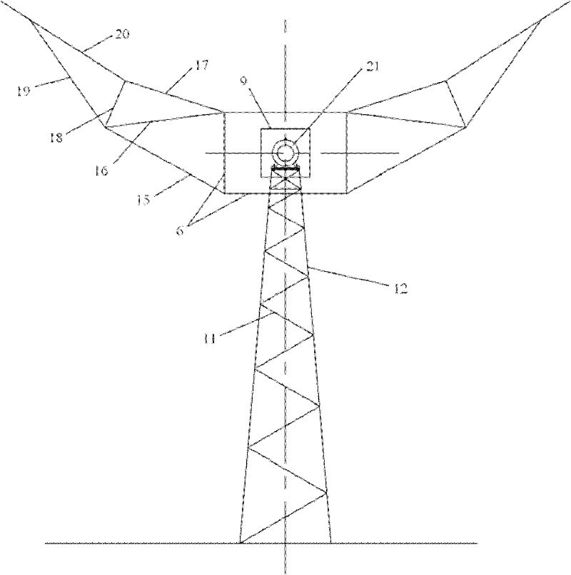
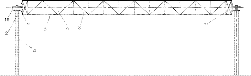
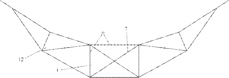
[0028] In this embodiment, each beam 5, column 12, reinforcement ribs, etc. are all made of Q235-B steel. The steel needs to undergo supplementary inspection, and the carbon content is not more than 0.22% or the welding test is required to ensure that the weldability is qualified. In this embodiment, the fixing bolts are all common grade C bolts.

[0029] The beams 5 are 4 square steel tubes with a length of 9000 to 14000 mm, and the 4 beams 5 are fixed together by 16 fixed structures. In each fixed structure, two 700 mm long square steel tubes are connected vertically to the two adjacent beams 5 and 2 A 1000mm-long square steel pipe is transversely connected to two adjacent beams 5 to form a rectangular frame s...


PUM


Abstract

The invention belongs to the technical field of grooved light-gathering solar thermal power generation and particularly relates to a space truss type grooved solar thermal power generation heat collector element bracket. The bracket comprises a space truss, rotating shaft assemblies, bearing assemblies and phi-shaped support leg members, wherein the bearing assemblies are arranged at the tops of the two phi-shaped support leg members; the rotating shaft assemblies are arranged at two ends of the space truss and also arranged on the bearing assemblies, so that the space truss is erected between the two phi-shaped support leg members and can rotate along the rotating shaft assemblies; and n groups of dual-wing racks are fixed on the space truss along the length direction of the space truss.The space truss type grooved solar thermal power generation heat collector element bracket disclosed by the invention has a simple structure, thus the manufacturing cost is greatly reduced; the most of mechanical members can adopt prefabricated members, thus the production process is simplified; and the strength is high, thus optical performance of the heat collector during work period can be ensured.

Description

Technical field [0001] The invention belongs to the technical field of trough-type concentrating solar thermal power generation, and particularly relates to a space truss-type trough-type solar thermal power collector element support. Background technique [0002] Concentrated solar thermal power generation system (CSP) can be divided into three main technologies: trough, tower and dish according to different concentrating forms. Comparing the three technologies, the trough thermal power generation technology is the most mature. Trough concentrating solar thermal power system (CSP) technology is widely used in solar thermal power generation in the United States and Spain. In the 1980s, the United States had installed 354MW of power and has 25 years of commercial operation experience. As of March 2009, 419MW of solar thermal power generation in the United States has been put into commercial operation, all of which are trough solar thermal power generation systems. This fully pro...

Claims


Application Information

Patent Timeline
Patent Type & Authority Applications(China)
IPC IPC(8): F24J2/54
CPCY02E10/47
Inventor 李昌伟李雅菲邵玉梅
Owner GUODIAN LONGYUAN POWER TECH ENG
Why Eureka
Try Eureka