Source electrode driving circuit and display device

A technology of source drive and source current, applied in static indicators, instruments, etc., can solve problems such as restricting the application of current-driven pixel units and long programming time, and achieve faster programming speed, high programming accuracy, and good stability Effect

Active Publication Date: 2014-09-17
BOE TECH GRP CO LTD
View PDF6 Cites 0 Cited by
  • Summary
  • Abstract
  • Description
  • Claims
  • Application Information

AI Technical Summary

Problems solved by technology

However, the main problem is the parasitic capacitance of the switching transistor and the overlapping capacitance between the signal lines, which makes the current-driven circuit take a long time to program the pixel unit in the case of low grayscale and low current, which seriously restricts the current-driven circuit. Application of pixel unit in large area and high resolution display

Method used


Image

  • Source electrode driving circuit and display device
  • Source electrode driving circuit and display device
  • Source electrode driving circuit and display device

Examples


Embodiment Construction

[0034] The present invention will be further described in detail below through specific embodiments in conjunction with the accompanying drawings.

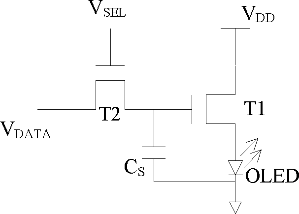
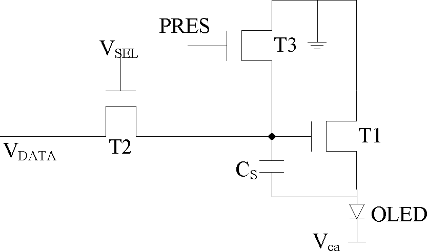
[0035] In each of the following embodiments, the control electrode of the transistor corresponds to the gate of the TFT, and the first current conduction electrode and the second current conduction electrode are reciprocal, that is, the first current conduction electrode can be the source or is the drain, and correspondingly, the second current conduction electrode may be the drain or the source. In addition, in the embodiment, the light emitting device is an organic light emitting diode (OLED) as an example for illustration.

[0036] Such as Figure 4 and Figure 5 As shown, the embodiment of the source drive circuit includes: a source current generation module, a clock signal generation module, a switch selection module, and a current-voltage conversion module; wherein, the source current generation module provides the data cu...


PUM


Abstract

The invention discloses a source electrode driving circuit and a display device. The source electrode driving circuit comprises a source electrode current generation module for generating a data current signal, a clock signal generation module for generating a clock signal, a current-voltage conversion module for converting the data current signal into a corresponding data voltage signal and outputting the data voltage signal to a corresponding data signal line, and a switch selection module for transmitting the data current signal output by the source electrode current generation module to the current-voltage conversion module or directly transmitting the data current signal to a corresponding data line under control of the clock signal. The source electrode driving circuit and the display device can accelerate the speed of current programming on the basis of being capable of ensuring the advantages of high-precision gray level control and high stability of a current type pixel structure, thereby meeting the requirements on high-resolution large-size display.

Description

technical field [0001] The invention relates to the technical field of display devices, in particular to a source driving circuit and a display device. Background technique [0002] OLED (Organic Light-Emitting Diode, Organic Light-Emitting Diode) organic electroluminescent display is an emerging flat-panel display device. The advantages of low power consumption, easy matching with integrated circuit drivers, high luminous brightness, wide range of operating temperature adaptation, light and thin volume, and easy realization of flexible displays make it have broad application prospects. [0003] According to different driving methods, OLED can be divided into two types: passive matrix driving (Passive Matrix Organic Light Emission Display, PMOLED) and active matrix driving (Active Matrix Organic Light Emission Display, AMOLED). Although the passive matrix driver has a simple process and low cost, it cannot meet the needs of high-resolution and large-size displays due to sho...

Claims


Application Information

Patent Timeline
Patent Type & Authority Patents(China)
IPC IPC(8): G09G3/20G09G3/32G09G3/3233
Inventor 张盛东梁逸南王龙彦廖聪维
Owner BOE TECH GRP CO LTD
Why Eureka
Try Eureka