Optical signal multiplexing method and optical multiplexer

An optical multiplexer and signal multiplexing technology, which is applied in the field of communication, can solve the problems of large insertion loss, large difference in optical power and optical field energy distribution, and large volume of optical layer multiplexers, so as to reduce the number of reflections and insertion loss small size effect

Active Publication Date: 2011-12-28
HUAWEI TECH CO LTD
View PDF4 Cites 10 Cited by
  • Summary
  • Abstract
  • Description
  • Claims
  • Application Information

AI Technical Summary

Problems solved by technology

[0008] In order to solve the disadvantages of the existing technology, such as the large size of the optical layer multiplexer, the large difference in the optical power and optical field energy distribution of each output channel, and the large insertion loss when coupled with the optical fiber, the present invention provides a A method for multiplexing optical signals and a design scheme for an optical multiplexer

Method used


Image

  • Optical signal multiplexing method and optical multiplexer
  • Optical signal multiplexing method and optical multiplexer
  • Optical signal multiplexing method and optical multiplexer

Examples


Embodiment 1

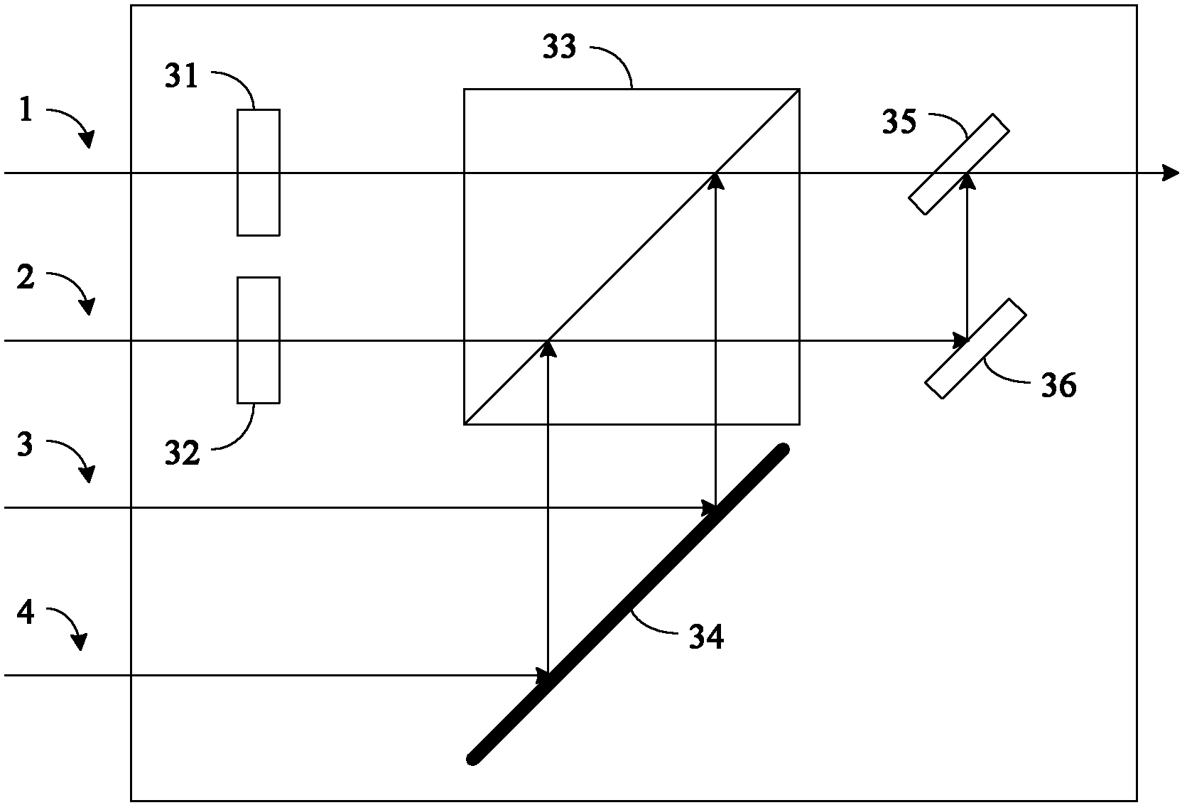
[0045] This embodiment provides an optical multiplexer, which is used to multiplex at least four optical signals into one optical signal, and its structure is as follows Figure 2A As shown, it at least includes: a polarization adjustment element 31 , a polarization adjustment element 32 , a polarization beam combiner 33 , an optical path changing element 34 , a beam combiner 35 and an optical path changing element 36 .

[0046] The polarization adjustment element 31 adjusts the polarization state of the first optical signal 1 input to the optical multiplexer, so that the first optical signal 1 and the third optical signal 3 input to the polarization beam combiner 33 can be polarization-combined Beamer 33 synthesizes one optical signal.

[0047] The polarization adjustment element 32 adjusts the polarization state of the second optical signal 2 input to the optical multiplexer, so that the second optical signal 2 and the fourth optical signal 4 input to the polarization beam c...

Embodiment 2

[0061] This embodiment provides an optical multiplexer, which is used to multiplex at least four optical signals into one optical signal, and its structure is as follows Figure 3A As shown, it at least includes: a polarization adjustment element 41 , a polarization adjustment element 42 , a polarization beam combiner 43 , a polarization beam combiner 44 , an optical path changing element 45 , an optical path changing element 46 , a beam combiner 47 and an optical path changing element 48 .

[0062] The polarization adjustment element 41 adjusts the polarization state of the first input optical signal 1, so that it can be combined with the second optical signal 2 input to the polarization beam combiner 43 after being input to the polarization beam combiner 43 to form All the way to the light signal.

[0063] The polarization adjustment element 42 adjusts the polarization state of the input third optical signal 3, so that it can be combined with the fourth optical signal 4 inpu...

Embodiment 3

[0078] Corresponding to the optical multiplexer provided in Embodiment 1 and Embodiment 2, the embodiment of the present invention also provides a method for multiplexing optical signals, which is used to multiplex at least four optical signals into one optical signal. The process is as follows Figure 4 shown, including:

[0079] Step S1: adjusting the polarization state of the first optical signal of the at least four optical signals, so that the first optical signal and the second optical signal of the at least four optical signals can be multiplexed by polarization being combined into one optical signal; adjusting the polarization state of the third optical signal of the at least four optical signals so that the third optical signal and the fourth optical signal of the at least four optical signals can Combined into one optical signal through polarization multiplexing;

[0080] Step S2: Combining the first optical signal with the adjusted polarization state and the second...


PUM


Abstract

The present invention discloses a method for multiplexing optical signals and an optical multiplexer, relates to the field of optical communication, and is used for multiplexing at least four optical signals into one optical signal. The method provided by the present invention comprises the steps of: adjusting polarization states of two optical signals in the four optical signals to be multiplexed so as to make the polarization states of the adjusted two optical signals are respectively different from the polarization states of the other two optical signals, preferredly are mutual orthogonal; merging the one adjusted optical signal and the one unadjusted optical signal into one optical signal through polarization multiplexing; and merging the two optical signals obtained by the polarization multiplexing into one optical signal, thereby realizing multiplexing four optical signals into one optical signal. When the multiplexing in the scheme of the present invention is performed, the various optical signals are multiplexed into one optical signal based on the polarization multiplexing, the differences of optical path lengths that the various optical signals go through are little, thus distribution differences of optical power and light field energy of the various optical signals are little when the various optical signals are multiplexed together.

Description

technical field [0001] The invention relates to the communication field, in particular to an optical signal multiplexing method and an optical multiplexer. Background technique [0002] The rapid growth of network traffic has promoted the continuous growth of the line card capacity of routers and transmission equipment. , Pluggable optical transceiver modules have gradually become a hot spot in the industry. [0003] In recent years, various module manufacturers have successively launched 100GE client-side modules. Most of the solutions on the sending side use four discrete TOSA (Transmitter Optical Subassembly) devices, and an external optical layer MUX (multiplexer, multiplexer) ) The device combines the light output by the 4-channel TOSA into a single-mode optical fiber for transmission. The goal of many manufacturers' next-generation optical modules is to reduce the size and power consumption of key components on the transmitting side by designing integrated TOSAs, and...

Claims


Application Information

Patent Timeline
Patent Type & Authority Applications(China)
IPC IPC(8): H04Q11/00
CPCG02B6/2773G02B27/283G02B6/2713H04J14/06
Inventor 宋小鹿蒋文斌邓琪曾理
Owner HUAWEI TECH CO LTD
Why Eureka
Try Eureka