Device and method for compounding and forming central flange pipe joint from pipe blank in single-step and multi-directional way

A technology of compound forming and tube billet, which is applied in the direction of mechanical equipment, engine components, metal extrusion dies, etc., can solve the problems of different plastic processing technology, low material utilization rate, low production efficiency, etc., to save processing time and materials The effect of high utilization rate and less process

Active Publication Date: 2013-08-21
JIANGSU UNIV
View PDF4 Cites 0 Cited by
  • Summary
  • Abstract
  • Description
  • Claims
  • Application Information

AI Technical Summary

Problems solved by technology

[0002] Pipe joints are key parts of pipeline connections in petroleum, chemical, metallurgy, machinery and other industries. They can be produced by various processes such as casting, welding, plastic processing, and cutting processing. The pipe joints have high strength and good corrosion resistance. Therefore, the mass production of most pipe joints adopts the plastic processing process. In contrast, the cutting process is used to produce the middle flange pipe joints. Low, low material utilization
[0003] The shape and structure of pipe joints are different, and the plastic processing technology is also different. Generally, stamping, forging, extrusion and other processes can be used. Compared with the end flanges, the difficulty of using plastic processing methods in the production of the middle flange lies in the polymer material in the middle. , forming is difficult and requires multiple formings. At present, there is no report on the use of pipe blanks for one-step multi-directional composite forming of the middle flange pipe joint.

Method used


Image

  • Device and method for compounding and forming central flange pipe joint from pipe blank in single-step and multi-directional way
  • Device and method for compounding and forming central flange pipe joint from pipe blank in single-step and multi-directional way
  • Device and method for compounding and forming central flange pipe joint from pipe blank in single-step and multi-directional way

Examples


example

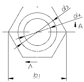
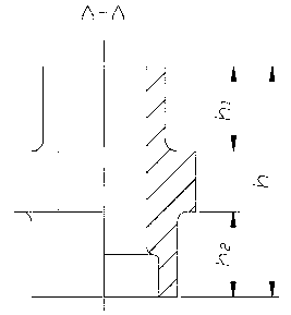
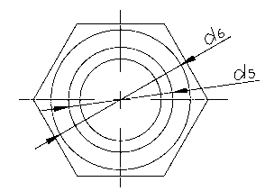
[0033] Example: A Typical Mid-Flanged Fitting, Small End OD d 3 =20mm, height h 1 =14mm, outer diameter of big end d 6 =24mm, height h 2 =14mm, through hole diameter d 4 =12mm, big end step hole diameter d 5 =17.8mm, the hexagonal flange in the middle is simplified into a cylindrical flange with a diameter of 30mm, and the overall height of the pipe joint in the middle flange h =38mm; the material is 15#; the outer diameter of the tube blank is used d 2 =28mm, inner diameter d 1 =13mm, tube blank length L =27.5; Die mandrel 5 is placed in the outer ring 4 of the die, the tube blank is placed on the mandrel 5 of the die, and the punch 3 is installed in the regular hexagonal cavity 6 at the upper end of the outer ring of the die, located in the tube The billet is extruded from top to bottom on a 2000KN hydraulic press, the metal filling is in good condition, and the metal flow is consistent with the design.

[0034] The one-step multi-directional compound forming...


PUM

PropertyMeasurementUnit
heightaaaaaaaaaa
diameteraaaaaaaaaa
diameteraaaaaaaaaa

Abstract

The invention discloses a device and a method for compounding and forming a central flange pipe joint from a pipe blank in a single-step and multi-directional way. The method comprises the following steps of: applying enough pressure on an appropriate pipe billet serving as a blank to make the whole pipe billet plastically deformed; forming a central flange of the pipe joint by upsetting; and inversely extruding to form a small head end part of the pipe joint and positively extruding to form a large head end part of the pipe joint, so metal upwards, downwards and radially flows, the forming force is small, and the number of stations is small. Compared with a cutting pipe joint, the invention has the advantages of high material utilization ratio and production efficiency and good metal flow structure, and is particularly applicable for production of high-pressure pipe joints.

Description

technical field [0001] The invention relates to a central flange pipe joint, in particular to a device and method for one-step multi-directional composite forming of a central flange pipe joint from pipe blanks. Background technique [0002] Pipe joints are key parts of pipeline connections in petroleum, chemical, metallurgy, machinery and other industries. They can be produced by various processes such as casting, welding, plastic processing, and cutting processing. The pipe joints have high strength and good corrosion resistance. Therefore, the mass production of most pipe joints adopts the plastic processing process. In contrast, the cutting process is used to produce the middle flange pipe joints. Low, low material utilization. [0003] The shape and structure of pipe joints are different, and the plastic processing technology is also different. Generally, stamping, forging, extrusion and other processes can be used. Compared with the end flanges, the difficulty of usin...

Claims


Application Information

Patent Timeline
Patent Type & Authority Patents(China)
IPC IPC(8): B21K1/16B21C23/03B21C25/02B21C25/04B21J5/08
Inventor 王雷刚黄瑶田辉王楚翘
Owner JIANGSU UNIV
Why Eureka
Try Eureka