Device and method for one-step multi-directional composite forming of middle flange pipe joint of round bar material

A composite forming, round bar technology, applied in forging/pressing/hammer devices, mechanical equipment, engine components, etc., can solve the problems of different plastic processing processes, low material utilization, and difficult forming, and save processing time. , High material utilization rate, material saving effect

Inactive Publication Date: 2015-08-26
JIANGSU UNIV
View PDF5 Cites 1 Cited by
  • Summary
  • Abstract
  • Description
  • Claims
  • Application Information

AI Technical Summary

Problems solved by technology

[0002] Pipe joints are key parts of pipeline connections in petroleum, chemical, metallurgy, machinery and other industries. They can be produced by various processes such as casting, welding, plastic processing, and cutting. Due to the high production efficiency of plastic processing, material saving and low processing cost The pipe joints have high strength and good corrosion resistance. Therefore, the mass production of most pipe joints adopts the plastic processing process. In contrast, the cutting process is used to produce the middle flange pipe joints. Low, low material utilization
[0003] The shape and structure of pipe joints are different, and the plastic processing technology is also different. Generally, stamping, forging, extrusion and other processes can be used. Compared with the end flanges, the difficulty of using plastic processing methods in the production of the middle flange lies in the polymer material in the middle. , the forming is difficult and requires multiple formings. At present, there is no report on the use of round bars to form the middle flange in one step and multi-directional.

Method used


Image

  • Device and method for one-step multi-directional composite forming of middle flange pipe joint of round bar material
  • Device and method for one-step multi-directional composite forming of middle flange pipe joint of round bar material
  • Device and method for one-step multi-directional composite forming of middle flange pipe joint of round bar material

Examples


example

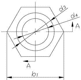
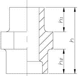
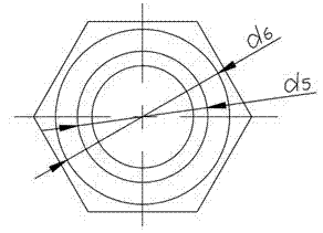
[0037] Example: A typical middle flange pipe joint, small end outer diameter d 3 =20mm, height h 1 =14mm, the outer diameter of the big end d 6 =24mm, height h 2 =14mm, through hole diameter d 4 =12mm, the diameter of the stepped hole at the big end d 5 =17.8mm, the central hexagonal flange is simplified into a cylindrical flange with a diameter of 30mm, the total height of the central flange pipe joint h =38mm; material is 15#; round bar diameter is used d 1 =24mm, l =26.5mm; Put the round bar on the die core 4, install the punch 2 in the upper pit 5 of the punch upsetting ring, and place it on the round bar, from top to top on a 1600KN hydraulic press Extrusion is performed under the pressure, the metal filling condition is good, and the metal flow condition is consistent with the design.

[0038] The one-step multi-directional composite forming of the middle flange pipe joint method of the present invention can make the metal flow up, down and radially in multiple directions at ...


PUM

PropertyMeasurementUnit
heightaaaaaaaaaa
diameteraaaaaaaaaa
diameteraaaaaaaaaa

Abstract

The invention discloses a method for forming a central flange pipe joint from a round rod material in a one-step, multidirectional and composite manner. The method comprises the following steps of: using the round rod material as a blank; after perforating a conical head male die, upsetting, extruding and forming the central flange part of the pipe joint; simultaneously, upwardly and reversely extruding and downwardly and forwardly extruding to form the upper end and the lower end of the pipe joint. According to the method disclosed by the invention, metal can flow in multiple directions, such as upward, downward and radial simultaneously; the deformation force is small; fewer work stations are required; compared with the pipe joint cutting, the material utilization rate is high; the production efficiency is high; the metal flow organization is good; and the method is especially applied to production of high-pressure pipe joints.

Description

Technical field [0001] The invention relates to a middle flange pipe joint, in particular to a device and a method for forming a middle flange pipe joint by round bar materials in one step and multiple directions. Background technique [0002] Pipe joints are the key parts of pipeline connection in petroleum, chemical, metallurgy, machinery and other industries. They can be produced by casting, welding, plastic processing, cutting processing and other processes. Due to the high production efficiency of plastic processing, materials are saved and processed The pipe joints have high strength and good corrosion resistance. Therefore, most of the mass production of pipe joints use plastic processing methods. In contrast, the use of cutting processing methods to produce the middle flange pipe joints requires more procedures and production efficiency. Low, low material utilization. [0003] The shape and structure of the pipe joints are different, and the plastic processing technology i...

Claims


Application Information

Patent Timeline
Patent Type & Authority Patents(China)
IPC IPC(8): B21K1/16B21C23/03B21C25/02B21J5/08B21J13/02
Inventor 王雷刚黄瑶田辉王楚翘
Owner JIANGSU UNIV
Why Eureka
Try Eureka