
Sensing optical cable for synchronously monitoring temperature and pressure in oil well tubing in distribution mode

A distributed monitoring and sensing optical cable technology, which is applied in the real-time monitoring of pressure and temperature in the oil pipe, can solve the problems of low pressure value accuracy, high temperature resistance, corrosion resistance and poor mechanical strength, etc., to achieve convenient collection and strong The effect of compatibility and structural symmetry

Active Publication Date: 2012-01-04
YANGTZE OPTICAL FIBRE & CABLE CO LTD
View PDF5 Cites 16 Cited by
  • Summary
  • Abstract
  • Description
  • Claims
  • Application Information

AI Technical Summary

Problems solved by technology

[0010] The purpose of the present invention is to overcome the defects and problems of low accuracy of obtained pressure value, high temperature resistance, corrosion resistance and poor mechanical strength existing in the prior art, and to provide a method for obtaining a pressure value with high accuracy Sensing optical cable with high temperature resistance, corrosion resistance and good mechanical strength for simultaneous distributed monitoring of temperature and pressure in oil well tubing

Method used


Image

  • Sensing optical cable for synchronously monitoring temperature and pressure in oil well tubing in distribution mode
  • Sensing optical cable for synchronously monitoring temperature and pressure in oil well tubing in distribution mode

Examples


Embodiment 1

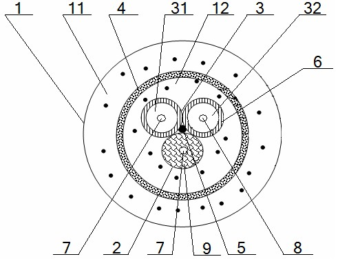
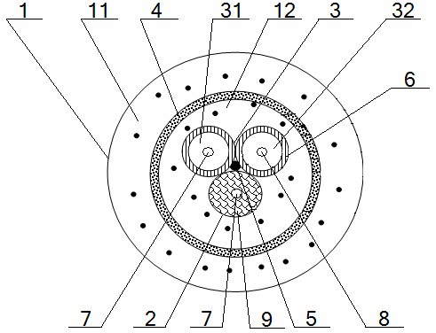
[0041] Sensing optical cable for simultaneous distributed monitoring of temperature and pressure in oil well tubing, including a circular cross-section high-strength high-temperature-resistant and corrosion-resistant material layer 1 and ring-shaped metal steel strips 4 and metal steel strips 4 set inside The high-strength, high-temperature-resistant and corrosion-resistant material layer 1 is divided into an outer protective buffer layer 11 and an inner protective buffer layer 12. The interior of the inner protective buffer layer 12 is arranged in the shape of a character. There are No. 1 high-temperature-resistant armored loose-tube optical fiber 31, and No. 2 resistant High-temperature armored loose-buffered optical fiber 32 and high-temperature-resistant and corrosion-resistant tight-buffered optical fiber 2, and among the first high-temperature-resistant armored loose-buffered optical fiber 31, the second high-temperature-resistant armored loose-buffered optical fiber 32, a...


PUM

PropertyMeasurementUnit
Diameteraaaaaaaaaa
The inside diameter ofaaaaaaaaaa
Thicknessaaaaaaaaaa

Abstract

The invention provides a sensing optical cable for synchronously monitoring the temperature and pressure in oil well tubing in a distribution mode, which comprises a high-strength heat-resistant corrosion-resistant material layer which is divided into an outer protective buffer layer and an inner protective buffer layer by a metal steel strip, wherein a first heat-resistant armored loose tube optical fiber, a second heat-resistant armored loose tube optical fiber and a heat-resistant corrosion-resistant tight tube optical fiber are distributed in the Chinese character of 'Pin' in the inner protective buffer layer; metal strengthened cores are respectively arranged in the middle parts of the first heat-resistant armored loose tube optical fiber, the second heat-resistant armored loose tubeoptical fiber and the heat-resistant corrosion-resistant tight tube optical fiber; and a heat-resistant singlemode optical fiber is arranged in the first heat-resistant armored loose tube optical fiber, a heat-resistant multimode optical fiber is arranged in the second heat-resistant armored loose tube optical fiber, and a heat-resistant singlemode optical fiber is arranged in the heat-resistant corrosion-resistant tight tube optical fiber. The sensing optical cable designed by the invention has the advantages of higher accuracy of finally-obtained pressure value, higher heat resistance and corrosion resistance, high mechanical strength, high safety and unified lattice performance and is convenient to manufacture and construct.

Description

technical field [0001] The invention relates to a sensing optical cable, in particular to a sensing optical cable for simultaneous distributed monitoring of temperature and pressure in oil wells, and is particularly suitable for simultaneously monitoring the temperature and pressure in oil wells of oil wells such as deep layers, heavy oil, and thermal recovery. real-time monitoring. Background technique [0002] With the development of optical fiber technology, optical fiber sensing application technology has gradually been applied to the field of oil well testing. As the transmission medium and sensing medium of optical signals, optical cable has become the core component of the optical fiber logging system of oil wells. The optical cables currently used are generally transmission optical cables. Although this type of transmission optical cable can provide multiple effective protections for the optical fiber that implements signal transmission and temperature signal monito...

Claims


Application Information

Patent Timeline
IPC IPC(8): G02B6/44G01D21/02
Inventor 黄莎
Owner YANGTZE OPTICAL FIBRE & CABLE CO LTD
Learn More