LCD projector light source system employing three sheet LED lamp plates

A technology of LED light source and LED light board is applied in the direction of using image reproducer, light source, point light source of projection device, etc., and can solve the problems of high price of high-power LED lamp wick, complicated optical path structure of projector, and influence on popularization and application, etc. Achieve significant practical effects, enhance utilization efficiency, and simplify the production process.

Inactive Publication Date: 2012-01-04
TIANJIN IAT SCI & TECH
View PDF6 Cites 3 Cited by
  • Summary
  • Abstract
  • Description
  • Claims
  • Application Information

AI Technical Summary

Problems solved by technology

The two light sources can better meet the brightness requirements of large-format projection, but the optical path structure of the projector is relatively complicated, the volume is large, and it needs to be warmed up for 1 to 2 minutes before it is turned on. Accounting for about 1 / 4 to 1 / 5 of the total price of the equipment, it is a relatively large economic burden for projector users, and it is difficult for ordinary families to bear
[0003] At present, the known optical path system of 3LCD projectors on the market has problems such as complex structure, large volume, multiple fans for heat dissipation, and short life of the light source, which is not conducive to wide application.
As the world's low-carbon economy, energy conservation and environmental protection dominate the development trend of people's consumption life, technological progress provides new opportunities for the innovation of electronic equipment. Light-emitting diodes (LEDs) are semiconductor light sources with long life and environmental protection, but in In the past period of time, due to the high price of high-brightness and high-power LED wicks, popularization and application have been affected.

Method used


Image

  • LCD projector light source system employing three sheet LED lamp plates
  • LCD projector light source system employing three sheet LED lamp plates

Examples


Embodiment Construction

[0011] Below in conjunction with the accompanying drawings and preferred embodiments, the specific implementation, structure and features provided by the present invention are described in detail as follows:

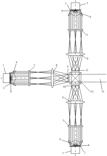
[0012] Such as figure 1 As shown, an LCD projector light source system using three LED light panels, the system includes a heat dissipation device 1, an LED light source circuit board 2, a red LED light source 3, a green LED light source 4, a blue LED light source 5, a TIR lens 6, Fly eye lens 7, Kohler lighting lens group 8, red signal LCD panel and polarizer group 9, green signal LCD panel and polarizer group 10, blue signal LCD panel and polarizer group 11, synthetic prism (X-Cube) 12 and projection objective lens 13.

[0013] The red LED light source 3, the green LED light source 4, and the blue-red LED light source 5 are installed together with the heat sink 1 and the LED light source circuit board 2 respectively. Red, green, and blue are three independent light pa...


PUM


Abstract

The invention relates to an LCD projector light source system employing three sheet LED lamp plates. The system comprises a heat radiation apparatus, a light source circuit board, a red LED light source, a green LED light source, a blue LED light source, a TIR lens, a fly-eye lens, a Kohler illumination lens group, a red LCD panel and polaroid group , a green LCD panel and polaroid group , a blue LCD panel and polaroid group, a synthesized prism and a projection objective. The TIR lens enables a light emitted by an LED to be collected to greatest extent and to be collimated; the collimated light beam is subdivided and focused by the fly-eye lens and then is projected on the LCD panels by the Kohler illumination lens group, so that uniformity of reception of the luminous energy on the LCD panels can be ensured; and the light that penetrates the LCD panels is synthesized by the synthesized prism and then is projected on a screen by the projection objective to carry out imaging. According to the invention, an LED light source is employed; the utilization of the TIR lens enables complexity of an optical path to be further reduced; therefore, an integral structure of a projector is simplified and a volume of the projector is reduced; moreover, a utilization rate of the luminous energy is enhanced to the greatest extent and a practical effect is substantial.

Description

technical field [0001] The invention relates to a projector light source system, in particular to an LCD projector light source system using three LED lamp panels. Background technique [0002] For many years, projectors have been public equipment in the fields of business activities and education. They are characterized by the ability to easily obtain large screens, display digital and analog images, and can be used as super-large-screen TVs. They are gradually becoming popular in household appliances from public equipment. ; At present, the light sources of 3LCD projectors on the market mostly use UHE ultra-high pressure mercury bulbs and metal halide bulbs, which are ideal light sources widely used in medium and low-end projectors. The advantage of UHE ultra-high pressure mercury bulbs is that the price is moderate, and the brightness hardly decays before 4000 hours of use. Metal halide bulbs are cheaper than UHE, with high efficiency, high color rendering, and high colo...

Claims


Application Information

Patent Timeline
Patent Type & Authority Applications(China)
IPC IPC(8): G03B21/20F21V5/04F21V9/14F21Y101/02
CPCH04N9/3164H04N5/74H04N9/31G03B21/2033G03B21/14H04N9/3105H04N9/3155G03B21/2073
Inventor 靳张铝周烨锋吴向东刘喜章李海洋
Owner TIANJIN IAT SCI & TECH
Why Eureka
Try Eureka