Machining technique of turbine blade ring

A technology for steam turbine blades and processing technology, applied in the field of steam turbine manufacturing, can solve the problems of inconvenient processing, tight tolerance requirements, and difficulty in processing the extraction port of a guide vane ring steam seal groove.

Active Publication Date: 2012-01-11
SHANGHAI ELECTRIC POWER GENERATION EQUIPMENT CO LTD
View PDF4 Cites 10 Cited by
  • Summary
  • Abstract
  • Description
  • Claims
  • Application Information

AI Technical Summary

Problems solved by technology

[0004] There are certain difficulties in the processing of the guide vane ring steam seal groove 1, the meridian surface surface 2 and the steam extraction port.
The guide vane ring steam seal groove 1 is composed of left and right step surfaces 11, left and right elbow grooves 12, straight groove 13 and arc groove 14 at the bottom of the straight groove 13. The structure is relatively complicated. If it is formed by a machine tool, it is easy to produce errors. However, the manufacturing requirements of the guide vane ring seal groove 1 are particularly high and the tolerance requirements are tight, so it is difficult to meet the processing requirements by one-time molding method
The inner straight hole 3 of the steam extraction port is located on the meridian surface 2, and the outer inclined hole 4 is located on the outer circular inclined surface. Therefore, the openings of the inner straight hole 3 and the outer inclined hole 4 are located on the curved surface, which is difficult to locate during processing, especially prone to deviation
The meridian surface 2 is composed of two concave-convex arcs and two straight lines tangent to each other. The shape is very irregular and it is very inconvenient to process.

Method used


Image

  • Machining technique of turbine blade ring
  • Machining technique of turbine blade ring
  • Machining technique of turbine blade ring

Examples


Embodiment Construction

[0017] Preferred embodiments of the present invention will be described in detail below in conjunction with the accompanying drawings.

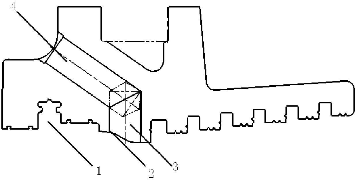
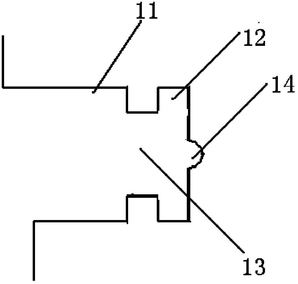
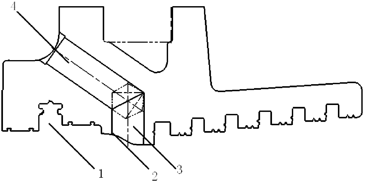
[0018] Such as figure 1 , 2 As shown, in the process of processing the turbine blade retaining ring, when processing the guide vane ring seal groove 1, firstly design the corresponding machining tool and measuring tool according to the shape line of the steering guide vane ring seal groove, and then Before processing, the reference planes for measurement are processed on the radial and axial surfaces of the turbine blade holding ring to ensure the tolerance requirements of the matching surfaces of the steam seal groove of the steering guide vane ring, so that the processing quality can reach the best state.

[0019] When processing, first use a straight groove cutter to roughly cut the size of the straight groove 13 and the left and right step surfaces 11 of the steering guide vane ring steam seal groove 1. In terms of technology, consider l...


PUM


Abstract

The invention discloses a machining technique of a turbine blade ring. In the machining technique, the machining of a guide blade ring steam seal groove is characterized in that different tools are used to respectively process a straight flute, left and right step surfaces, left and right elbow grooves and an arc groove on the guide blade ring steam seal slot according to a certain sequence, so that the machining precision of the guide blade ring steam seal groove can be effectively ensured, and the machining quality of the guide blade ring steam seal groove can also be ensured. When a steam extracting opening is machined, small planes are respectively arranged at corresponding positions on an excircle inclined surface and a meridian plane curved surface, so that a drilling hole can be conveniently positioned, thus the machining precision of the steam extraction opening can be ensured. With the adoption of the machining technique of the turbine blade ring, the machining precision of the turbine blade ring can be effectively increased and the quality of the turbine blade ring can be improved, moreover, the production efficiency can be effectively increased and the machining time can be shortened.

Description

technical field [0001] The invention relates to the field of steam turbine manufacturing, in particular to a processing method for a steam turbine blade holding ring. Background technique [0002] In order to improve the efficiency of the steam turbine unit, it is usually necessary to install a steam turbine blade holding ring on the steam turbine, and install an embedded steam seal at the inner diameter of the blade holding ring and the inner diameter of the diaphragm, so that a smaller diameter can be formed between the shroud of the moving blade and the rotor. To the gap, thereby reducing the steam leakage between stages of the steam turbine and improving the efficiency of the steam turbine unit. [0003] The existing stator blade holding ring mainly includes a structural form of a partition plate groove, a T-shaped steam seal groove, a straight steam seal groove, and a cylinder matching positioning groove. However, for the 100MW ultra-high pressure double-extraction con...

Claims


Application Information

Patent Timeline
Patent Type & Authority Applications(China)
IPC IPC(8): B23P15/00
Inventor 蔡振铭王敏周辉峰
Owner SHANGHAI ELECTRIC POWER GENERATION EQUIPMENT CO LTD
Why Eureka
Try Eureka