Eureka AIR delivers breakthrough ideas for toughest innovation challenges, trusted by R&D personnel around the world.

Device for treating liquefiable foundation by using vibratory hammer pipe and treatment method thereof

A technology of liquefied foundations and vibratory hammers, applied in soil protection, foundation structure engineering, sheet pile walls, etc., can solve the problems of strong vibration energy affecting the surrounding environment, muddy water pollution, and weak ability to penetrate the soil layer. Achieve the effects of low noise and vibration, convenient movement, and improved construction efficiency

Inactive Publication Date: 2012-01-11
JIAN YAN FOUND ENG
View PDF10 Cites 4 Cited by
  • Summary
  • Abstract
  • Description
  • Claims
  • Application Information

AI Technical Summary

Problems solved by technology

This method overcomes the technical problems of weak penetrating ability of vibrating tube-immersed gravel piles, muddy water pollution at the site of vibrating gravel piles, and large vibration energy of the dynamic compaction method affecting the surrounding environment.

Method used


Image

  • Device for treating liquefiable foundation by using vibratory hammer pipe and treatment method thereof
  • Device for treating liquefiable foundation by using vibratory hammer pipe and treatment method thereof
  • Device for treating liquefiable foundation by using vibratory hammer pipe and treatment method thereof

Examples


Embodiment 1

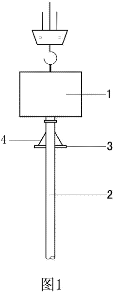
[0056] Embodiment one sees figure 1As shown, a device for treating liquefied ground with a vibratory hammer tube includes a vibratory hammer 1 and a core tube 2. The core tube 2 is arranged under the vibratory hammer 1 and connected with the vibratory hammer 1 by flange or welding. The power of the vibratory hammer motor is 10KW-80KW, the power of the vibratory hammer motor is 10KW-80KW, the core tube is a seamless steel pipe with a circular or polygonal cross-section, and the diameter of the circular cross-section or the diameter of the inscribed circle of the polygon It is 100mm ~ 300mm, and its free end is open or closed. A fixed pressure plate 3 is hooped on the outer surface of the core tube, and the pressure plate 3 is circular or square. Strengthening ribs 4 distributed radially from the axis of the core tube are arranged between the pressure plate 3 and the core tube 2 .

Embodiment 2

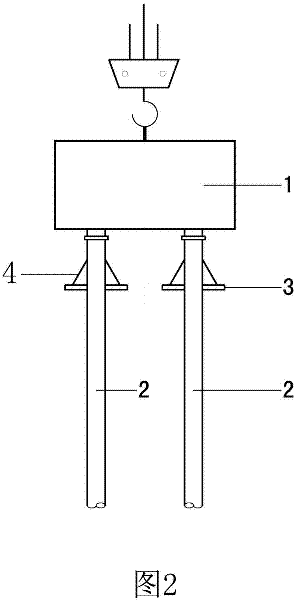
[0057] Embodiment two see figure 2 , the difference from Embodiment 1 is that the core tube is a double tube.

Embodiment 3

[0058] Embodiment three see image 3 and Figure 4 , different from Embodiment 1, the pressure plate 3 is detachably connected to the core pipe through bolts, and the position of the pressure plate can be adjusted along the axial direction of the core pipe. The position of the pressure plate can be liquefied according to the thickness and The length of the core tube is determined, and the pressure plate connected with the core tube is generally close to the vibrating hammer. The core tube is provided with a set of reinforcing wings along its axial direction, each set of reinforcing wings has 4 pieces, and each piece of reinforcing wings is welded to the outer surface of the core tube. The reinforcing wings are steel plates with a height of 400mm to the same length as the core pipe and a width of 0-800mm. The reinforcing wings are trapezoidal reinforcing wings 5 ​​.


PUM


Abstract

The invention relates to a device for treating a liquefiable foundation by using a vibratory hammer pipe and a treatment method thereof, belonging to the field of liquefiable foundation treatment devices and treatment techniques. By using a vibratory hammer pipe device formed by a core pipe which is arranged below a vibratory hammer, reinforcing wings and a pressurizing plate which are arranged on the core pipe, loose liquefiable soil is compacted and the goal of eliminating the liquefiable foundation is achieved. The device and the construction method have the advantages of strong soil layer penetration capacity, low noise, low manufacturing cost, high efficiency, environmental friendliness and the like, can be widely used for the treatment of liquefiable foundations, especially the treatment of foundations with thick liquefiable sand layers.

Description

technical field [0001] The invention relates to a ground treatment device and a ground treatment method using the device, in particular to a device for treating liquefied ground and a ground treatment method using the device. Background technique [0002] Existing common methods for eliminating or partially eliminating the liquefaction of sandy soil and silt include vibrating sinking tube crushed stone piles, vibrating compacted crushed stone piles and dynamic compaction. [0003] The construction technology of vibrating tube-immersed gravel pile is to use a large-scale tube-immersing pile machine to sink the pile tube with a diameter of 325mm, 377mm or larger into the sand or silt through the vibration of the vibrating hammer, and drive the pile tube to move through the vibrating hammer. Vibrate and compact the soil between the piles while feeding materials to the pile tube to form a gravel pile. The pile tube for construction can use a valve pile tip or a prefabricated pil...

Claims


Application Information

Patent Timeline
Patent Type & Authority Applications(China)
IPC IPC(8): E02D7/18E02D3/08E02D5/66
Inventor 闫明礼张东刚佟建兴张震孙训海
Owner JIAN YAN FOUND ENG
Why Eureka
Eureka Blog
Learn More