
Work-piece locating and bonding device

A technology for bonding devices and workpieces, applied in work accessories, manufacturing tools, stone processing equipment, etc., can solve the problems of inconsistent thickness uniformity of the adhesive layer, insufficient operation convenience, inconsistent thickness uniformity, etc., and achieve the thickness of the adhesive layer. Controllable, consistent adhesive layer thickness, consistent thickness uniformity

Active Publication Date: 2012-01-18
峨嵋半导体材料研究所
View PDF4 Cites 3 Cited by
  • Summary
  • Abstract
  • Description
  • Claims
  • Application Information

AI Technical Summary

Problems solved by technology

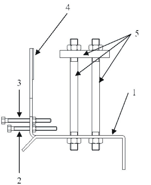
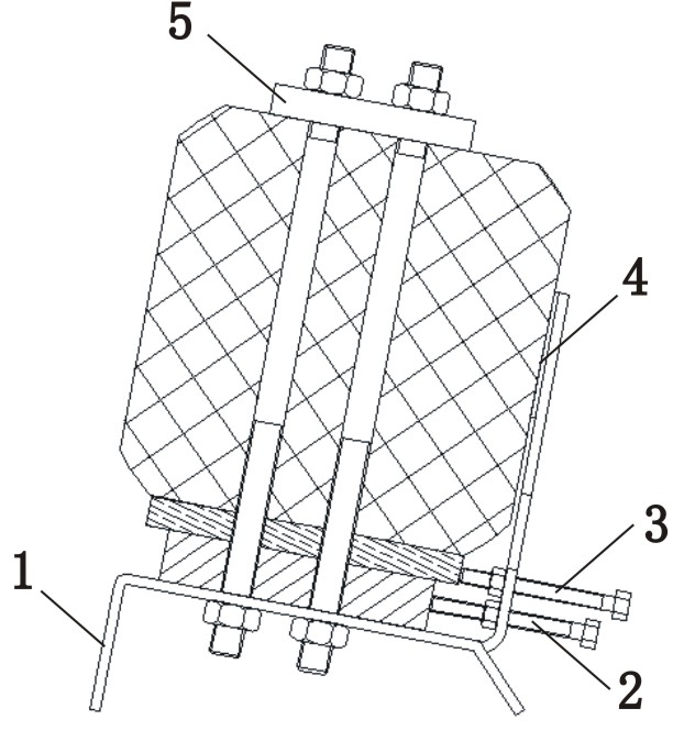
[0006] 1. The workpiece connector at the bottom is positioned with a two-point positioning screw. The accuracy of the positioning of the workpiece connector directly affects the overall positioning of the workpiece. Since the screw has rotational mobility, this positioning method is likely to cause inaccurate overall positioning. accurate;
[0007] 2. The angle between the operating platform of the whole device and the horizontal plane is relatively large, and the resin adhesive used in each bonding step will flow to the lower side, resulting in inconsistent thickness uniformity of the final adhesive layer. Inconsistencies in the thickness of the glue layer between workpieces will affect the cutting quality;
[0008] 3. The used workpiece fixing and pressing module needs to be pressed by tightening the nut on the top to ensure the firmness of the bonding. Since it is difficult to maintain a consistent degree of tightness by manually rotating the tightening nut, it will lead to the final The thickness of the adhesive layer is uncontrollable and the thickness uniformity is inconsistent;
[0010] 5. The device is used to complete the positioning and bonding between the workpiece connector and the cutting pad, and between the cutting pad and the workpiece. Only one workpiece can be bonded at a time. The operation is not convenient and the work efficiency is not high.

Method used


Image

  • Work-piece locating and bonding device
  • Work-piece locating and bonding device
  • Work-piece locating and bonding device

Examples


Embodiment

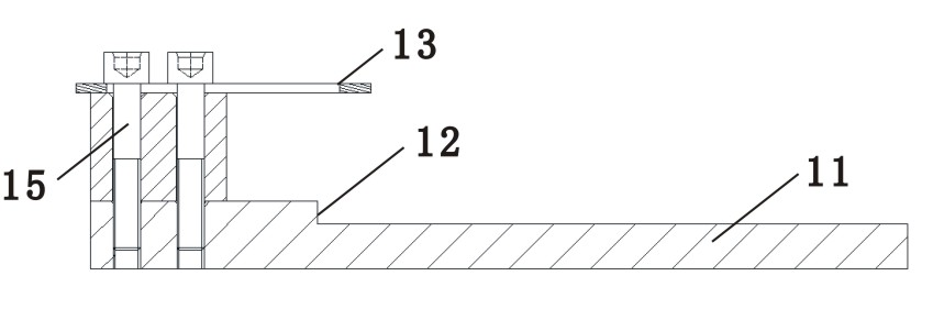
[0043]The workpiece positioning bonding device of the present invention includes a workpiece connecting piece and a cutting pad bonding device and a workpiece pad and a workpiece bonding device, wherein: the workpiece connecting piece and cutting pad bonding device includes a first placement base 11, a second A positioning ladder 12, a cutting pad positioning piece 13, a first fixed weight pressing block 14 and a vertical screw 15, the first positioning ladder 12 intersects vertically with the plane where the first placement base 11 is located, and the cutting The plane where the pad positioning piece 13 is located is parallel to the first placement base 11 , and the cutting pad positioning piece 13 , the first positioning ladder 12 and the first placement base 11 are fixedly connected by a screw rod 15 . The workpiece pad and the workpiece bonding device include a second placement base 21, a second positioning ladder 22, a reversible workpiece fixing fence 23, a tension rod 24...


PUM


Abstract

The invention discloses a work-piece locating and bonding device, which comprises a work-piece connecting piece and cut cushion block bonding device and a work-piece cushion block and work-piece bonding device. The work-piece connecting piece and cut cushion block bonding device comprises a first placing base, a first locating leaning ladder and a cut cushion block locating sheet. The planes in which the first locating leaning ladder and the first placing base are located are vertically crossed into a whole. The plane in which the cut cushion block locating sheet is located is parallel to the first placing base. The work-piece cushion block and work-piece bonding device comprises a second placing base, a second locating leaning ladder, a turnover work-piece fixing encircling rod, a tension rod, a fixed work-piece fixing encircling rod and a work-piece locating leaning plate. The bonding between a work-piece connecting piece and a cut cushion block and the bonding between a work-piece cushion block and a work-piece can be carried out independently by using the two devices. Both the two bonding devices are in double-station design, therefore, two work-pieces can be bonded simultaneously; the centring property and the consistency of the same multi-line cutting equipment for cutting the two work-pieces can be ensured; the operation is more convenient; and the working efficiency is high.

Description

technical field [0001] The invention relates to an auxiliary device for preparing workpieces for silicon chip processing wire cutting, in particular to a workpiece positioning and bonding device. Background technique [0002] During the processing of solar and semiconductor grade silicon wafers, especially the processing of solar silicon wafers, most of them use multi-wire cutting equipment for slicing. In order to achieve higher cutting efficiency and benefits, strive to make the multi-wire cutting machine realize with reasonable structural design, high motion and position accuracy, effective control and monitoring functions, and greater adaptability. [0003] The preparation of the cutting workpiece is one of the main operations before slicing the ingot, which mainly includes the bonding of the workpiece connector and the cutting pad, the bonding of the workpiece pad and the workpiece, and the fixing of the clamping guide rail and the workpiece connector. The accuracy of ...

Claims


Application Information

Patent Timeline
Patent Type & Authority Applications(China)
IPC IPC(8): B28D7/00
Inventor 宋亚尼陈琳彭文杨蜀罗恩富
Owner 峨嵋半导体材料研究所
Learn More