
Three-dimensional grid strain measurement method

A strain measurement and three-dimensional grid technology, applied in the field of measurement, can solve the problems of inability to measure the amount of strain, instability, limited measurement range, etc., and achieve the effects of complete automation of calculation, improved measurement efficiency, and small measurement limitations.

Active Publication Date: 2012-01-18
新拓三维技术(深圳)有限公司
View PDF4 Cites 21 Cited by
  • Summary
  • Abstract
  • Description
  • Claims
  • Application Information

AI Technical Summary

Problems solved by technology

The main disadvantages are: poor measurement accuracy, the size of the workpiece that can be measured cannot be too large, manual measurement is very cumbersome, it is repetitive labor, and the entire field strain cannot be measured
The main disadvantages are: the quality and stability of the sensor after pasting are affected by the aging of the substrate, adhesive, protective agent, and the quality of manual work during the pasting process, and it is prone to long-term drift and unstable quality. The amount of strain in some sheet metal forming processes, such as the amount of strain in the stamping process of sheet metal cannot be measured
The main disadvantages are: the camera needs to be calibrated before measurement, which is affected by CCD camera resolution, camera support system structure, environment, etc., the measurement accuracy is low, and the general strain measurement error is about 5%. Secondly, the measurement range is limited. Unsuitable and expensive to measure strain on large sheet metal formed parts

Method used


Image

  • Three-dimensional grid strain measurement method
  • Three-dimensional grid strain measurement method
  • Three-dimensional grid strain measurement method

Examples


Embodiment Construction

[0027] The present invention will be further described in detail below in conjunction with the accompanying drawings.

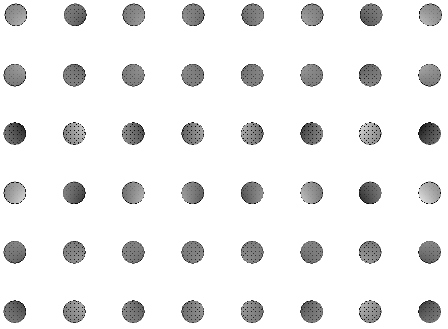
[0028] The present invention proposes a measurement method of three-dimensional grid strain, such as figure 1 shown. When measuring the strain of a sheet metal forming part, the first step is grid preparation. Before forming, the circular grid pattern (eg, figure 2 shown). Grid nodes are the centers of solid circles, and these solid circles are arranged vertically and horizontally to form a square grid structure. The size of the grid circle depends on the characteristics of the workpiece to be tested. When the deformation area is small and the strain changes sharply, a smaller grid circle diameter can be used, such as 1mm or even smaller, and the distance between the grid centers can be 2mm. The grid edges are 1mm apart. When the deformation area is large, a larger grid circle diameter can be used, such as 5mm, and the grid center spacing can be 10mm, s...


PUM


Abstract

The invention discloses a three-dimensional grid strain measurement method, which comprises the following steps of: step 1, grid preparation; step 2, sampling and shooting; step 3, picture orientation; step 4, grid node matching; step 5, grid node rebuilding; step 6, grid connection, step 7, grid optimization; and step 8, strain calculation. Through the operation steps, the method can be used for measuring the three-dimensional full field strain information in the metal plate material forming process, and the metal plate material forming performance and the advantages and disadvantages of the mold process design scheme can be evaluated, so the metal plate material forming quality is improved, the manufacture precision is improved, and the production cost is reduced. The three-dimensional grid strain measurement method has the characteristics that the measurement operation is convenient, the automation degree is high, the result is accurate and reliable, the measurement information is rich, the efficiency is high, and in addition, the non-contact measurement is realized.

Description

technical field [0001] The invention relates to a measurement method in the field of measurement technology, and further relates to a new method for measuring the three-dimensional full-field strain in the metal sheet forming process by means of optical photogrammetry. Background technique [0002] With the increasing application of sheet metal stamping technology, the complexity of the process is gradually increasing, and sheet metal tearing often occurs during the sheet metal forming process. The measurement of the three-dimensional full-field strain in the sheet metal forming process can evaluate the sheet metal forming performance and the pros and cons of the mold process design, improve the forming quality, improve the manufacturing accuracy, and reduce the production cost. The original measurement methods mainly include mechanical method, electrical measurement method and binocular stereo vision measurement method. [0003] The mechanical measurement method is a tradi...

Claims


Application Information

Patent Timeline
IPC IPC(8): G01B11/16G01C11/00G01C11/08
Inventor 梁晋史宝全唐正宗郭翔胡浩李磊刚王永信
Owner 新拓三维技术(深圳)有限公司
Learn More