Calibration method of response ratio parameter of infrared detector

An infrared detector and calibration method technology, applied in photometry, instruments, measuring devices, etc., can solve problems such as affecting the efficiency and accuracy of batch measurement, unstable laser output power, and difficulty in accurately measuring optical power, etc. Achieve the effect of improving calibration efficiency and accuracy, wide applicability, and ensuring accuracy

Inactive Publication Date: 2012-01-18
NORTHWEST INST OF NUCLEAR TECH
View PDF6 Cites 15 Cited by
  • Summary
  • Abstract
  • Description
  • Claims
  • Application Information

AI Technical Summary

Problems solved by technology

However, since the light intensity of the above-mentioned light source is very weak, and its power is even weaker after being split by the grating, it is difficult to accurately measure the light power after splitting, and it is also difficult to theoretically calculate the radiation characteristics and grating diffraction parameters of the broadband light source. Therefore, it can only be used for the relative measurement of the responsivity; the laser light source absolute measurement method uses a laser as a light source to measure the absolute responsivity of the detector at this wavelength. laser power
Due to the uneven spatial distribution of the output beam of the laser and the small effective photosensitive surface of the detector, when measuring a large number of detectors, it is necessary to measure the laser power and the response of the detector at the corresponding laser position twice for each detector signal, it is necessary to use a precision optical adjustment frame to precisely adjust the placement position of each detector, which will ultimately affect the efficiency and accuracy of batch measurement; in addition, when measuring the detector responsivity of special wavelengths such as mid-infrared Instable laser output power or high operating costs limit the application of this method

Method used


Image

  • Calibration method of response ratio parameter of infrared detector
  • Calibration method of response ratio parameter of infrared detector
  • Calibration method of response ratio parameter of infrared detector

Examples


Embodiment Construction

[0033] The idea of ​​the present invention is to use the method of combining the blackbody source with the narrow-band filter to obtain calibration light with uniform optical power density distribution and stable power at the photosensitive surface of the detector. The detector is installed on the fixing seat, and the outer shell of the detector is used for positioning. It is convenient to replace and does not need to adjust the placement position of the detector, thereby realizing the absolute responsivity calibration of batch photodetectors.

[0034] Taking the calibration of the absolute responsivity of the infrared detector at 3.8 μm as an example, the calibration method and calibration device of the present invention are introduced below:

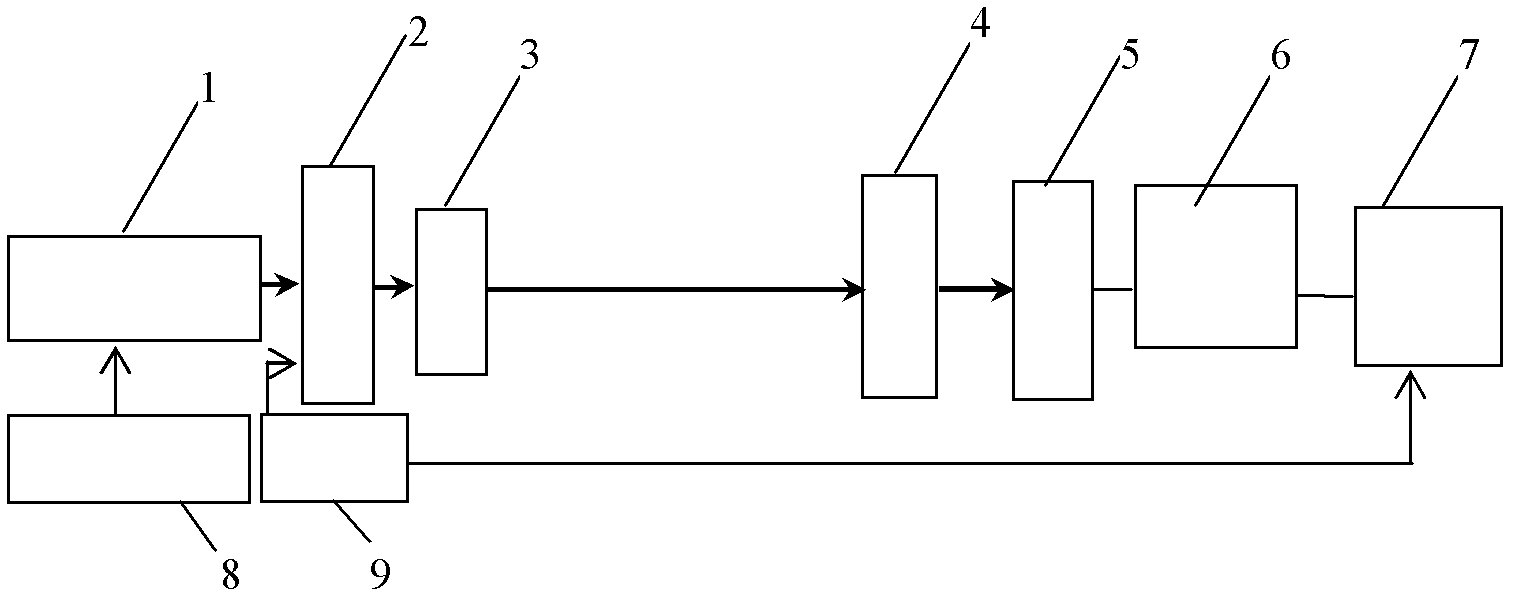
[0035] The absolute responsivity measurement principle of the infrared detector is as follows: figure 1 As shown, the radiated light from the blackbody source 1 is frequency-modulated by the optical chopper 2 , then output through the ...


PUM


Abstract

The invention discloses a calibration method of absolute response ratio of an infrared detector and a device thereof. By using the method of combining a blackbody origin and a narrow band pass filter, the absolute response ratio parameter of the detector under an appointed wavelength is acquired. According to the method, the blackbody origin is adopted as a calibration light source, so the stability of the uniformity of spatial output light spots is guaranteed; the placement positions of the detectors does not need to be precisely adjusted during calibration measurement, so the calibration efficiency and the precision of batch detectors are greatly improved; and meanwhile, power parameter of light irradiated onto the surfaces of the detectors is acquired through a theoretical calculation method, so errors in the power measurement of weak light signals are overcome. Through changing the wavelength parameter of the pass filter and the blackbody temperature, the method can be applied to parameter calibration of the detectors at various wavelengths, and the applicability is high.

Description

technical field [0001] The invention relates to a method for calibrating the responsivity parameter of a photoelectric detector, in particular to a method for calibrating the absolute responsivity of an infrared detector. Background technique [0002] Infrared detectors are the core components of laser power / energy density distribution measurement equipment. The number of infrared detectors used in this equipment is as many as hundreds. Accurate measurement of the responsivity parameters of the detectors is a prerequisite for determining the indicators of the measurement equipment. Responsivity refers to the ratio of the signal generated by the detector to the incident optical power of the wavelength at a specified wavelength. To achieve its absolute measurement, it is necessary to accurately measure the optical power of the wavelength incident on the detector and the signal generated by the detector. . [0003] The existing responsivity measurement methods mainly include b...

Claims


Application Information

Patent Timeline
Patent Type & Authority Applications(China)
IPC IPC(8): G01J1/00
Inventor 王平吴勇闫燕杨鹏翎冯国斌陈绍武宇文璀蕾
Owner NORTHWEST INST OF NUCLEAR TECH
Why Eureka
Try Eureka