
Method for controlling mass analysis device by utilizing triangular wave signals

A quality analysis device and signal control technology, applied in the field of control, can solve problems such as signal distortion, affecting the resolution of the quality analysis device, and large mutations in the rectangular wave signal, so as to improve the resolution, improve the confinement efficiency, and simplify the quality analysis device. Effect

Inactive Publication Date: 2012-01-18
INST OF CHEM CHINESE ACAD OF SCI
View PDF1 Cites 8 Cited by
  • Summary
  • Abstract
  • Description
  • Claims
  • Application Information

AI Technical Summary

Problems solved by technology

The RF AC signal has different waveforms, the most commonly used is the sinusoidal signal. Since the sinusoidal signal is restricted by the discharge voltage, the movement frequency of the sample ions is also limited by the sinusoidal signal voltage, which affects the resolution of the mass analyzer.
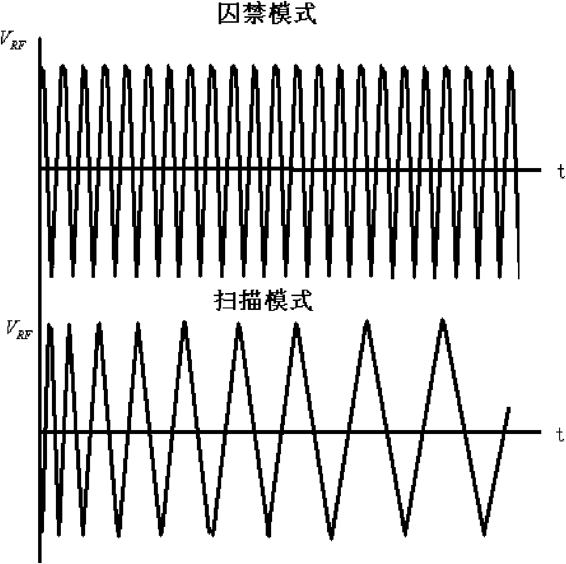
A control method different from the traditional sinusoidal signal has also been proposed. For example, the digital ion trap proposed by Ding Li et al. can also achieve the same function as a sinusoidal signal by providing a rectangular wave signal, but the rectangular wave signal has a large mutation, which is likely to cause signal distortion.

Method used


Image

  • Method for controlling mass analysis device by utilizing triangular wave signals
  • Method for controlling mass analysis device by utilizing triangular wave signals
  • Method for controlling mass analysis device by utilizing triangular wave signals

Examples


Embodiment Construction

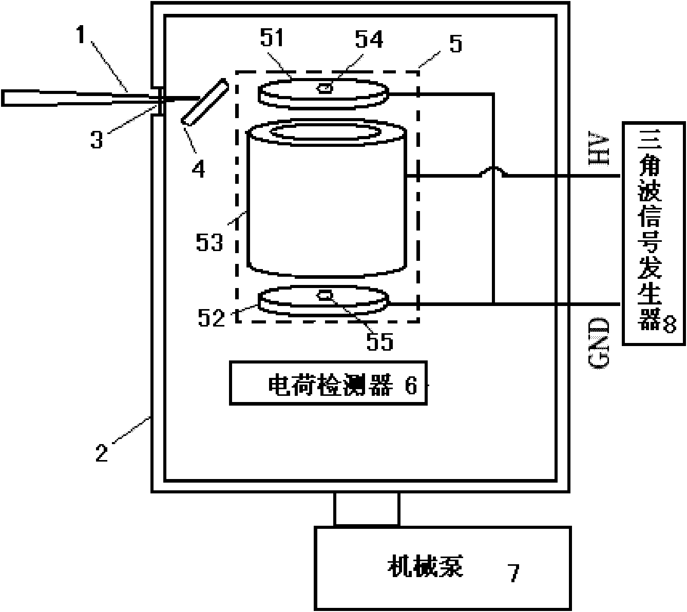
[0014] Mass analysis devices mainly include ion traps and quadrupoles. Among them, ion traps are divided into two-dimensional linear ion traps and three-dimensional rotating ion traps according to the confinement space of ions. Among them, the two-dimensional linear ion trap and the quadrupole can trap sample ions in two-dimensional space, and the three-dimensional ion trap can trap sample ions in three-dimensional space. The present invention takes a three-dimensional ion trap as an example to illustrate the method of controlling a mass analysis device using triangular wave signals, and other mass analysis devices can also be controlled according to the principle and method of the present invention. The method for controlling the mass analysis device by using a triangular wave signal according to the present invention will be described in detail below with reference to the accompanying drawings and embodiments.

[0015] Such as figure 1 As shown, the control system of the p...


PUM


Abstract

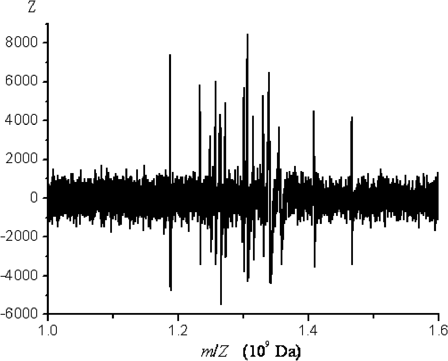
The invention relates to a method for controlling a mass analysis device by utilizing triangular wave signals. The method comprises the following steps of: (1) arranging a control system comprising a laser, a vacuum cavity, an optical window, a sample target, a cylindrical ion trap, a charge detector, a mechanical pump and a triangular wave signal generator; (2) dropwise adding a sample onto a silicon wafer and fixing the silicon wafer on the front face of the sample target; (3) vacuumizing the vacuum cavity, filling an inertial buffer gas in the vacuum cavity and regulating the air pressure; (4) irradiating laser emitted from the laser to the back face of the sample target through the optical window and generating sample ions by utilizing a laser induced sound wave desorption method; (5) enabling the sample ions to enter a ring electrode through a gap between a cover electrode and the ring electrode, selecting an embarment mode for the triangular wave signal generator, regulating an embarment voltage and embarring the sample ions in the cylindrical ion trap; and (6) selecting a scanning mode for the triangular wave signal generator, throwing the sample ions which are embarred in the cylindrical ion trap and have mass-to-charge rate more than a set threshold out of the cylindrical ion trap, and detecting the sample ions by the charge detector. The method disclosed by the invention is widely applied to measurement of mass ingredients of substances.

Description

technical field [0001] The invention relates to a control method, in particular to a method for controlling a mass analysis device by using a triangular wave signal. Background technique [0002] Mass spectrometer is a tool for measuring the quality of substances. It has the advantages of sensitivity, speed and accuracy, and plays an important role in the research of modern life sciences. The core part of a mass spectrometer is a mass analysis device, which mainly includes an ion trap and a quadrupole. Ion traps include two-dimensional linear ion traps and three-dimensional rotating ion traps. The two-dimensional linear ion trap includes electrode pairs in the three directions of x, y, and z. When detecting sample ions, the electrode pairs in the x and y directions are connected to the corresponding RF AC voltage and a DC voltage is applied to the electrode pair in the z direction. This traps the sample ions in the z-axis. The three-dimensional rotating ion trap can trap ...

Claims


Application Information

Patent Timeline
IPC IPC(8): H01J49/02H01J49/16H01J49/42
Inventor 聂宗秀周晓煜熊彩侨王佳宁陈芮
Owner INST OF CHEM CHINESE ACAD OF SCI
Learn More