Self-locking fuel cell sealing assembly structure

A technology for fuel cells and sealing components, which is applied to battery pack parts, electrical components, structural parts, etc., can solve problems such as auxiliary sealing methods that are not considered, achieve easy processing technology, realize processing technology, and improve stability and safety sexual effect

Inactive Publication Date: 2012-01-18
WUHAN UNIV OF TECH
View PDF5 Cites 19 Cited by
  • Summary
  • Abstract
  • Description
  • Claims
  • Application Information

AI Technical Summary

Problems solved by technology

[0010] The existing sealing rings are sealed by the vertical pressure of the guide plate or bipolar plate and the membrane electrode assembly (MEA), without considering another auxiliary sealing method, such as using the pressure difference of the gas to make the sealing ring seal. Self-locking (pressing) is formed in the channel to achieve the sealing effect

Method used


Image

  • Self-locking fuel cell sealing assembly structure
  • Self-locking fuel cell sealing assembly structure
  • Self-locking fuel cell sealing assembly structure

Examples


Embodiment 1

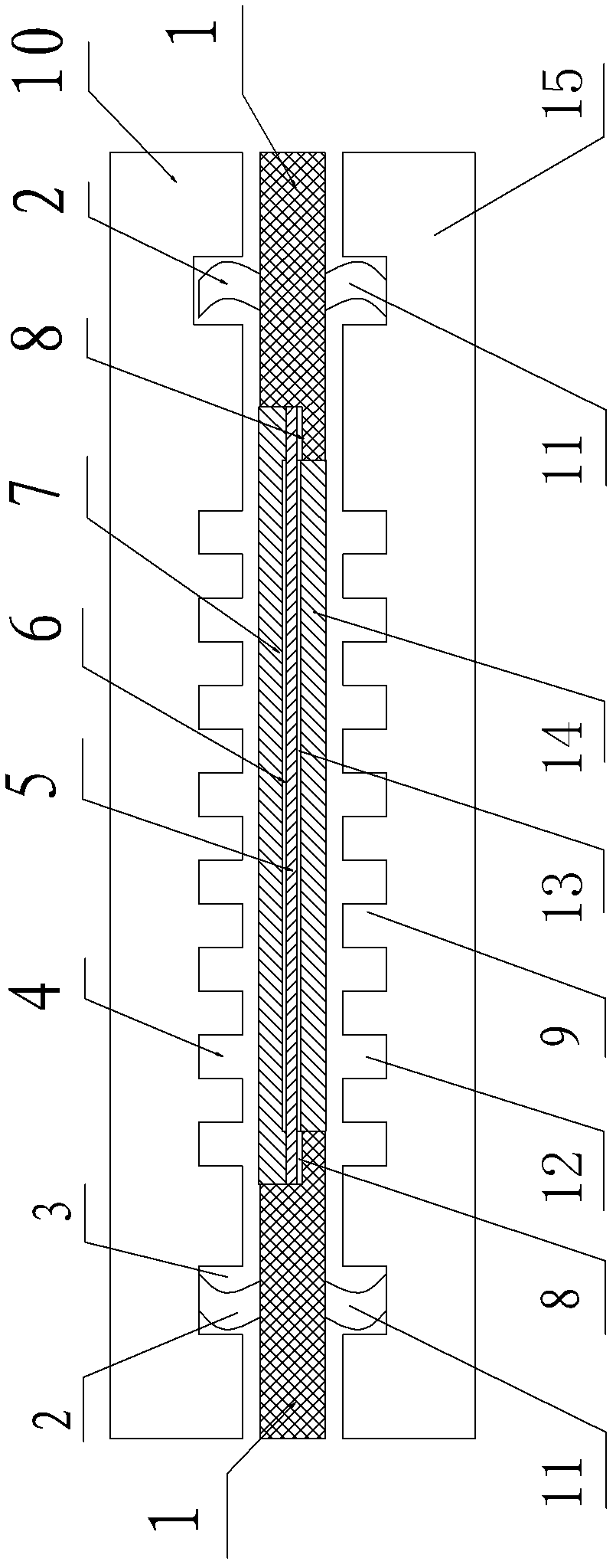
[0039] Such as Figure 1-5 As shown, a self-locking fuel cell sealing assembly structure, which involves a fuel cell cell, the fuel cell cell includes a bipolar plate and a membrane electrode assembly; the bipolar plate is composed of an upper unipolar plate 10 and a lower unipolar plate 15 , the upper unipolar plate 10 is provided with an upper flow channel 4 and an upper sealing channel 3, the upper channel 4 is located inside the annular upper sealing channel 3, an upper sealing ring 2 is provided in the upper sealing channel 3, and the lower unipolar The plate 15 is provided with a lower flow channel 12 and a lower sealing channel 16, the lower flow channel 12 is located inside the annular lower sealing channel 16, the lower sealing channel 16 is provided with a lower sealing ring 11, and the membrane electrode assembly is located in the upper unipolar Between the plate 10 and the lower unipolar plate 15, the upper channel 4 and the lower channel 12 are located at the memb...

Embodiment 2

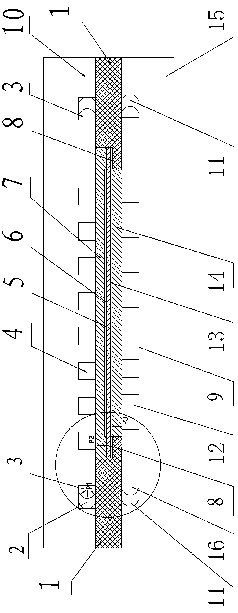
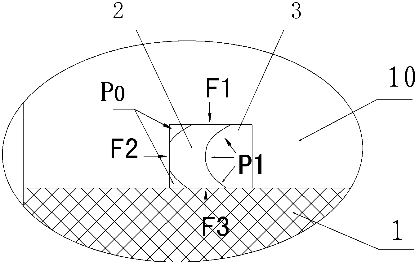
[0047] Such as Figure 6 Shown, a kind of self-locking fuel cell sealing assembly structure (another scheme), it relates to fuel cell monomer, and fuel cell monomer comprises bipolar plate, membrane electrode assembly; Bipolar plate is made up of upper unipolar plate 10 and lower Composed of unipolar plates 15, the upper unipolar plate 10 is provided with an upper flow channel 4, and the upper unipolar plate 15 is provided with a lower flow channel 12; the membrane electrode assembly is located between the upper unipolar plate 10 and the lower unipolar plate 15; The membrane electrode assembly includes a membrane electrode support part 1, a proton exchange membrane 5, an upper catalyst layer 6, an upper gas diffusion layer 7, a lower catalyst layer 13, and a lower gas diffusion layer 15. The membrane electrode support part 1 has a ring structure, and the membrane electrode support part 1 is provided with an annular support step on the inner wall of the annular chamber, the edg...

Embodiment 3

[0055] It is basically the same as Embodiment 2, the difference is that: the lower unipolar plate 15 is provided with a lower sealing channel 16 (the upper unipolar plate 10 is not provided with an upper sealing channel 3), and the lower flow channel 12 is located at the bottom of the ring. The inner side of the sealing channel 16, the lower sealing channel 16 is provided with a lower sealing ring 11, the cross-sectional shape of the lower sealing ring 11 is concave, the concave part of the lower sealing ring 11 faces the gas flow field area, and the lower flow channel 12 is located at At the membrane electrode supporting part 1 of the membrane electrode assembly, the upper unipolar plate 10 and the membrane electrode supporting part 1 of the membrane electrode assembly are bonded and fixed by the second sealing adhesive layer 17 .

[0056] The cross-sectional shape of the lower sealing ring 11 is V-shaped, C-shaped or U-shaped.

[0057] The number of the lower sealing grooves...


PUM


Abstract

The invention belongs to the technical field of fuel cell, specifically relates to a proton exchange membrane fuel cell sealing structure. The invention further discloses a self-locking fuel cell sealing assembly structure. The structure relates to a fuel cell monomer, wherein the fuel cell monomer comprises a bipolar plate and a membrane electrode assembly. The bipolar plate comprises an upper monopolar plate and a lower monopolar plate. The proton exchange membrane fuel cell sealing structure is characterized in that: cross-section shapes of an upper sealing ring and a lower sealing ring are concave, the concave parts of the upper sealing ring and the lower upper sealing ring are arranged toward a gas flow field region; a bonding agent layer is arranged between the edge part of a proton exchange membrane and an annular support bench of a membrane electrode support part to bond and fix the edge part and the annular support bench. The structure provided by the present invention has characteristics of simpleness, reliability, easy processing, outer leakage resistance and inner leakage resistance (blow-by of the anode and the cathode).

Description

technical field [0001] The invention belongs to the technical field of fuel cells, and in particular relates to a sealing structure of a proton exchange membrane fuel cell. Background technique [0002] Proton exchange membrane fuel cell (PEMFC) is a power generation device that directly utilizes hydrogen energy. PEMFC directly converts the chemical energy stored in hydrogen fuel and oxidant into electrical energy, and the energy conversion efficiency is high; the fuel cell is environmentally friendly and the only emission It is water. Therefore, fuel cell technology is considered to be the preferred clean and efficient power generation technology in the 21st century. [0003] When the proton exchange membrane fuel cell is working, under the action of the catalyst, the reaction that occurs is: [0004] [0005] The generated pollution-free water is directly discharged or recycled to humidify the gas, and the electrons generated by the electrode reaction reach the cathod...

Claims


Application Information

Patent Timeline
Patent Type & Authority Applications(China)
IPC IPC(8): H01M2/08
CPCY02E60/12Y02E60/10
Inventor 詹志刚叶东浩艾勇诚罗志平潘牧
Owner WUHAN UNIV OF TECH
Why Eureka
Try Eureka