Multiphase phase stagger parallel connection two-stage converter

A converter and phase-shifting technology, which is applied in the direction of converting DC power input to DC power output, instruments, adjusting electrical variables, etc. Effect of small ripple current

Inactive Publication Date: 2012-01-18
SHENZHEN MEGMEET ELECTRICAL CO LTD
View PDF4 Cites 29 Cited by
  • Summary
  • Abstract
  • Description
  • Claims
  • Application Information

AI Technical Summary

Problems solved by technology

However, when the resonance parameters of multiple resonant conversion circuits connected in parallel are relatively different, the output currents

Method used


Image

  • Multiphase phase stagger parallel connection two-stage converter
  • Multiphase phase stagger parallel connection two-stage converter
  • Multiphase phase stagger parallel connection two-stage converter

Examples


Embodiment 1

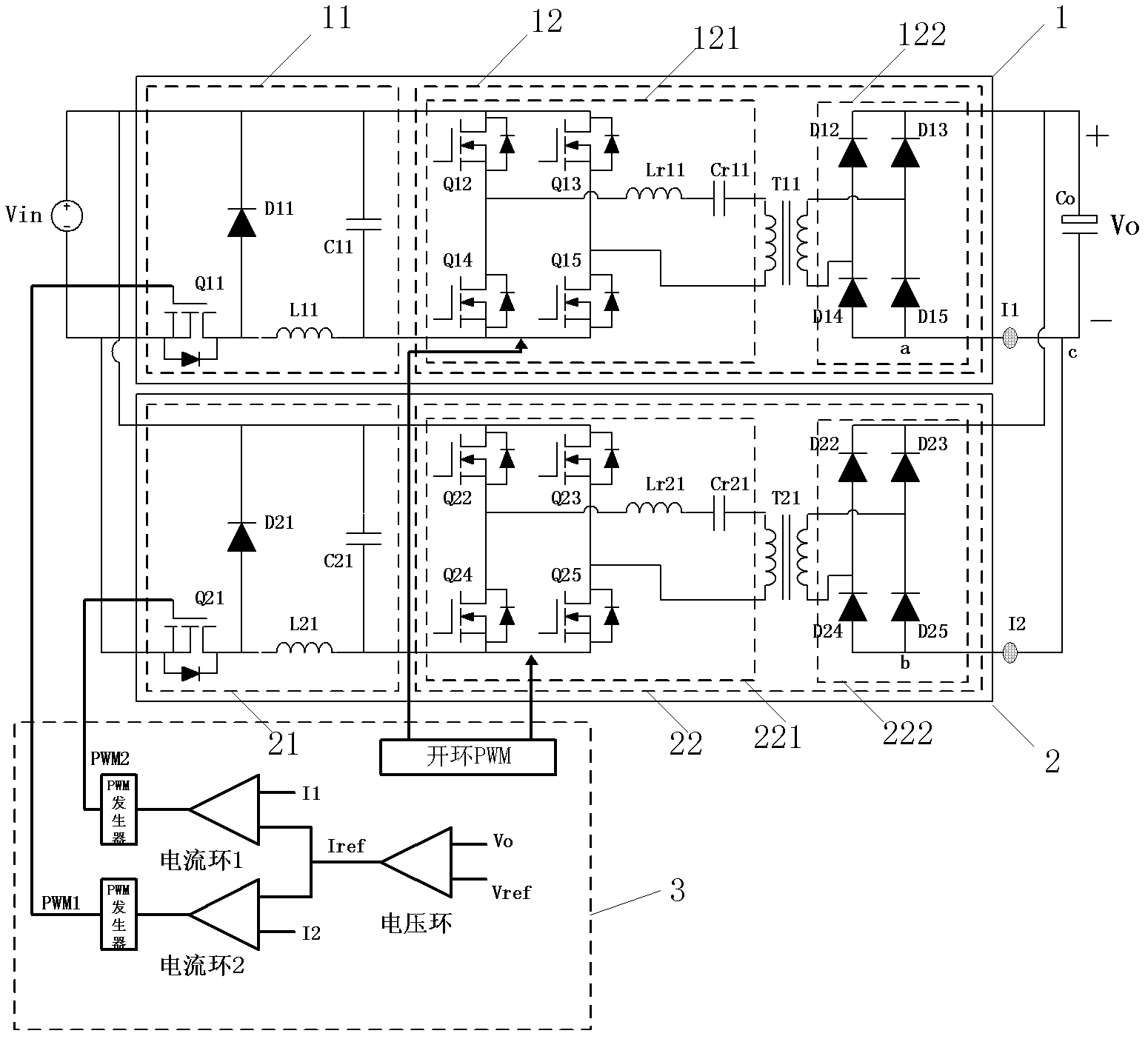
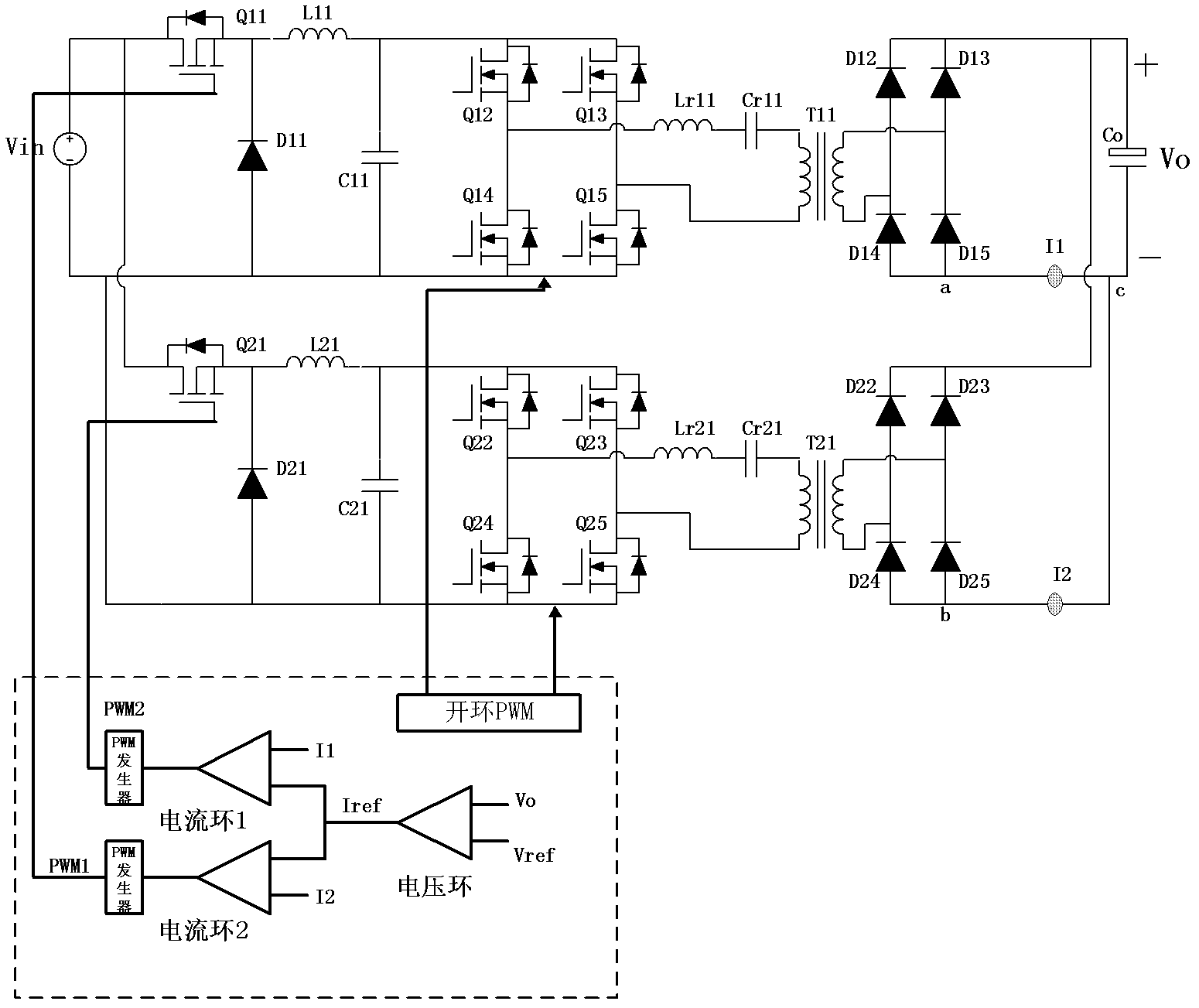
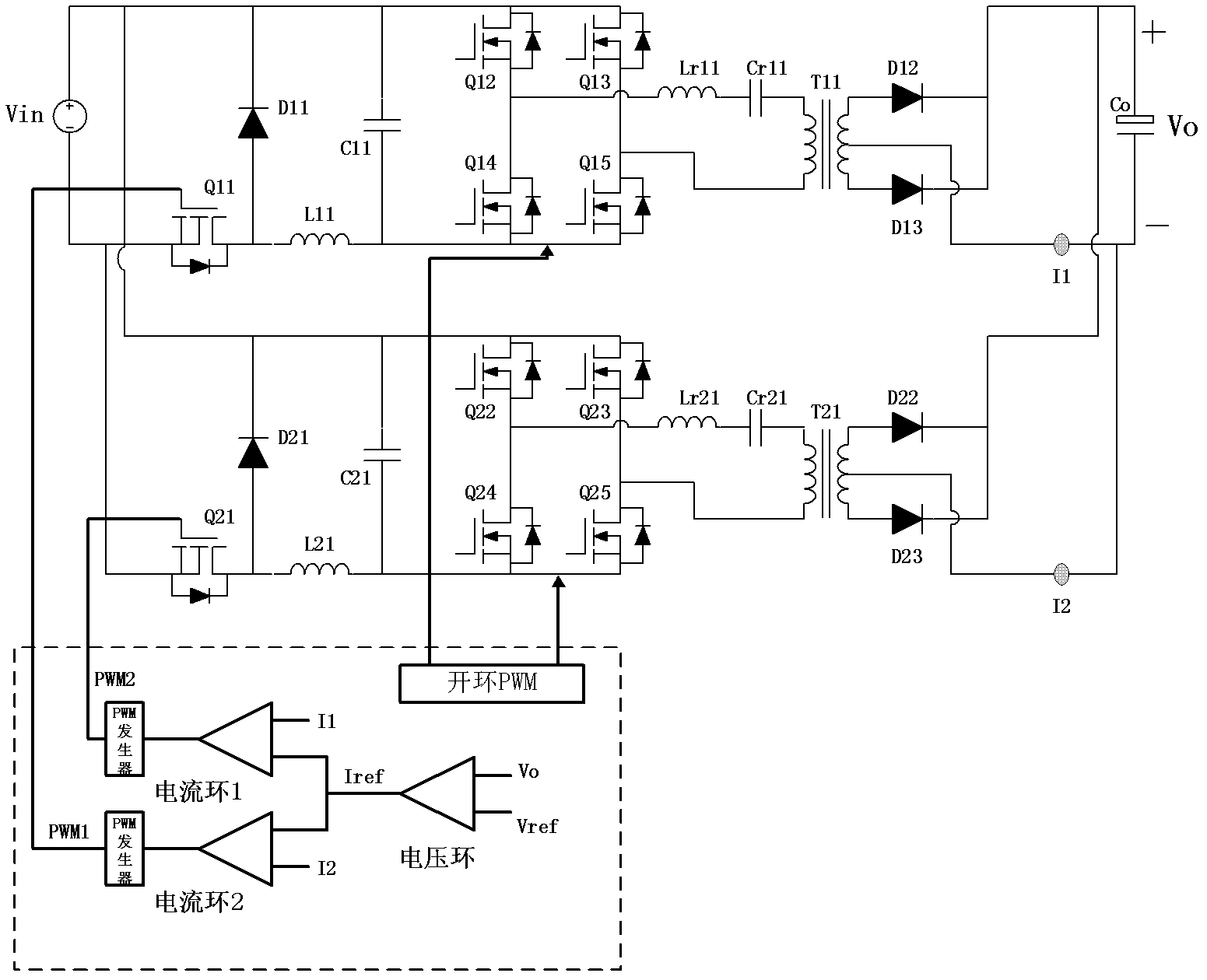
[0024] The pre-stage regulators 11 and 21 in Embodiment 1 are Buck regulators.

[0025] The first pre-regulator 11 includes a switch tube Q11, a diode D11, an inductance element L11 and a capacitor C11. One end of the switch tube Q11 is connected to the input negative bus, the other end is connected to the anode of the diode D11 and the first end of the inductance component L11, and the control end is connected to the control circuit 3; the cathode of the diode D11 is connected to the input positive bus; the capacitor C11 One end of is connected to the input positive bus, and the other end is connected to the second end of the inductor L11.

[0026] The second pre-regulator 21 includes a switch tube Q21, a diode D21, an inductance element L21 and a capacitor C21. One end of the switch tube Q21 is connected to the input negative bus, the other end is connected to the anode of the diode D21 and the first end of the inductance component L21, and the control end is connected to t...


PUM


Abstract

The invention discloses a multiphase phase stagger parallel connection two-stage converter which comprises a control circuit and two resonance conversion circuits with pre-stage regulators, the resonance conversion circuits are in parallel connection between an input positive and negative bus and an output positive and negative bus. Resonance circuits of the resonance conversion circuits with the pre-stage regulators open loop to work, and through the pre-stage regulators, output voltage control is realized. The control circuit controls each resonance conversion circuit to work with same frequency and phase stagger, and through current feedback control, same output current of each resonance conversion circuit is ensured. According to the invention, an uneven current problem of each resonance conversion circuit caused by parameter difference is solved, and ripple current of an input terminal and an output terminal of a circuit is reduced.

Description

[technical field] [0001] The present invention relates to a DC-DC conversion circuit, in particular to a multi-phase phase-staggered parallel dual-stage converter comprising at least two resonant conversion circuits with pre-stage regulators. [Background technique] [0002] The traditional resonant conversion circuit has the advantages of easy soft switching of the primary side switching tube, soft recovery of the secondary side switching tube, low switching loss and high efficiency. However, the resonant conversion circuit has a big disadvantage, that is, the output current ripple very big. One way to solve the above problems is to work in parallel with two or more resonant conversion circuits out of phase, which can greatly reduce the output ripple current. However, when the resonance parameters of multiple resonant conversion circuits connected in parallel are relatively different, the output currents of multiple conversion circuits are likely to be unbalanced, and even ...

Claims


Application Information

Patent Timeline
IPC IPC(8): H02M3/335H02M1/14
Inventor 高军陈利强
Owner SHENZHEN MEGMEET ELECTRICAL CO LTD
Why Eureka
Try Eureka