
Current controlled oscillator

A current control and oscillator technology, applied in electrical components, generating electrical pulses, pulse generation, etc., can solve the problem of no frequency output part description, and achieve the effect of saving power consumption and improving stability

Inactive Publication Date: 2012-01-18
CHINA KEY SYST & INTEGRATED CIRCUIT
View PDF5 Cites 22 Cited by
  • Summary
  • Abstract
  • Description
  • Claims
  • Application Information

AI Technical Summary

Problems solved by technology

[0004] In addition, the current control oscillator described in the prior art about the digital current control oscillator is composed of a voltage-current converter, a current generator controlled by a digital signal and a frequency output part, wherein the voltage-current converter and the digital signal control The current generators rely on the conversion of voltage to current, and are still affected by the input voltage, and this technology focuses on the description of the process of voltage-current conversion and the digital signal control of the current generator, and does not describe the frequency output part. describe

Method used


Image

  • Current controlled oscillator
  • Current controlled oscillator
  • Current controlled oscillator

Examples


Embodiment Construction

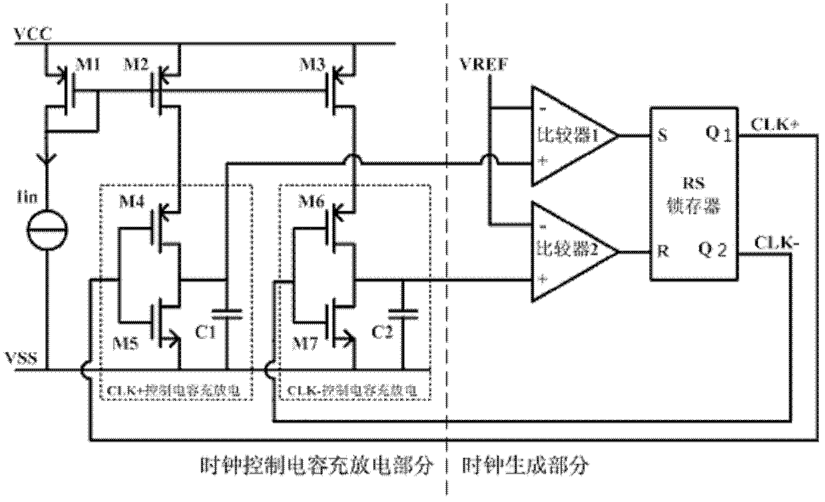
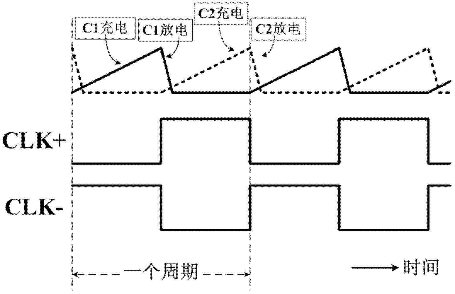
[0014] like figure 1 , figure 2 Shown are the schematic diagram of the structure of the current-controlled oscillator circuit of the present invention, the capacitor charging and discharging voltage waveform and the output clock signal waveform in the current-controlled oscillator circuit of the present invention.

[0015] figure 1 The middle input current Iin is mirrored to the M2 branch and the M3 branch through the current mirror, as the charging and discharging current of the capacitor C1 and the capacitor C2. The positive clock signal CLK+ controls M4 and M5, and then controls the capacitor C1 to enter the charging cycle (or enters the discharge cycle). At the same time, the negative clock signal CLK- is used to control M6 and M7, and then controls the capacitor C2 to enter the discharge cycle (or into the charging cycle). The specific working conditions are as follows: Assume that the initial value of the positive clock signal CLK+ is low potential, M4 controlled by ...


PUM


Abstract

The invention discloses a current controlled oscillator which comprises a clock control capacitor charge and discharge part and a clock generation part, wherein, the clock control capacitor charge and discharge part is composed of input current Iin, a current mirror and a charge and discharge capacitor of clock control, the clock generation part is composed of a comparator 1, a comparator 2, reference voltage VREF and an RS latch register; under the control of a clock signal outputted by the clock generation part finally, the clock control capacitor charge and discharge part carries out charge and discharge on a capacitor, a result of comparing polar plate voltage and reference voltage on the capacitor is used for determining setting or reset of the RS latch register, thereby clock signal output of certain frequency is realized. The current controlled oscillator has the following advantages: stability of output frequency is raised; output waveform of a 50% duty ratio can be obtained; circuit power consumption is saved.

Description

technical field [0001] The invention relates to a current-controlled oscillator, in particular to a current-controlled oscillator with a symmetrical structure that changes the output frequency of the oscillator by controlling the magnitude of the current. Background technique [0002] The function of the oscillator is to generate a stable, periodic time-domain pulse signal, and output the timing of the control logic circuit. Oscillators are widely used in integrated circuits and are a major component of many electronic systems, generating waveforms that can be used as clock signals in timing systems, or as amplitude- or frequency-modulated carrier signals for propagating information. Additionally, for display systems, oscillators can generate periodic converted voltages, or convert analog voltage or current data into frequencies. Oscillators are also critical building blocks in complex signal processing systems, such as frequency synthesizers. [0003] The traditional osci...

Claims


Application Information

Patent Timeline
IPC IPC(8): H03K3/011
Inventor 尹莉
Owner CHINA KEY SYST & INTEGRATED CIRCUIT
Learn More