Method for dewatering desorption gas for flue gas desulfurization and recycling condensate

A condensate and desorption technology, applied in chemical instruments and methods, steam condensation, separation methods, etc., can solve problems such as large increase in water volume, solution dilution, and reduction of rich liquid desorption degree

Inactive Publication Date: 2012-01-25
PANZHIHUA IRON AND STEEL +2
View PDF7 Cites 11 Cited by
  • Summary
  • Abstract
  • Description
  • Claims
  • Application Information

AI Technical Summary

Problems solved by technology

[0005] The patent application with the publication number CN200920350778.X discloses a regeneration tower, which mainly regenerates the desulfurization solution twice, and returns the condensate of the regenerated high-temperature gas to the desorption system (that is, the regeneration tower). The desulfurization gas will be heated, and the desorption energy consumption of desulfurization rich liquid will be reduced, but the desulfurization solution will still be diluted during the circulation process
In addition, the existing organic amine desulfurization technology is to perform one stage of absorption and one stage of desorption. The condensate of the desorbed gas is directly returned to the regeneration tower system. It takes a lot of heat for the condensate to rise from about 50 degrees to the desorption temperature. The degree of desorption of rich liquid is improved, and the energy consumption of desorption is increased.
[0006] In the above-mentioned patent application, in the flue gas washing process, the desulfurization system is difficult to maintain the water balance due to the moisture content of the flue gas, the demisting of the upper layer of the washing section, and the exhaust gas of the flue gas after washing, which will cause the solution to become dilution
At the same time, the condensed water in the desorbed high-temperature gas is returned to the regeneration tower, which does not effectively reduce the amount of water in the desorbed gas, thereby increasing the desulfurization energy consumption
[0007] In order to overcome the disadvantages of large increase of water in the existing flue gas desulfurization solution and high desorption energy consumption of the desulfurization and desorption condensate returned to the desorption system, a separate treatment of the gas condensate in the desorption system is needed, so as to solve the problem of increased water volume and energy consumption in the system Major and other issues

Method used


Image

  • Method for dewatering desorption gas for flue gas desulfurization and recycling condensate
  • Method for dewatering desorption gas for flue gas desulfurization and recycling condensate
  • Method for dewatering desorption gas for flue gas desulfurization and recycling condensate

Examples


Embodiment 1

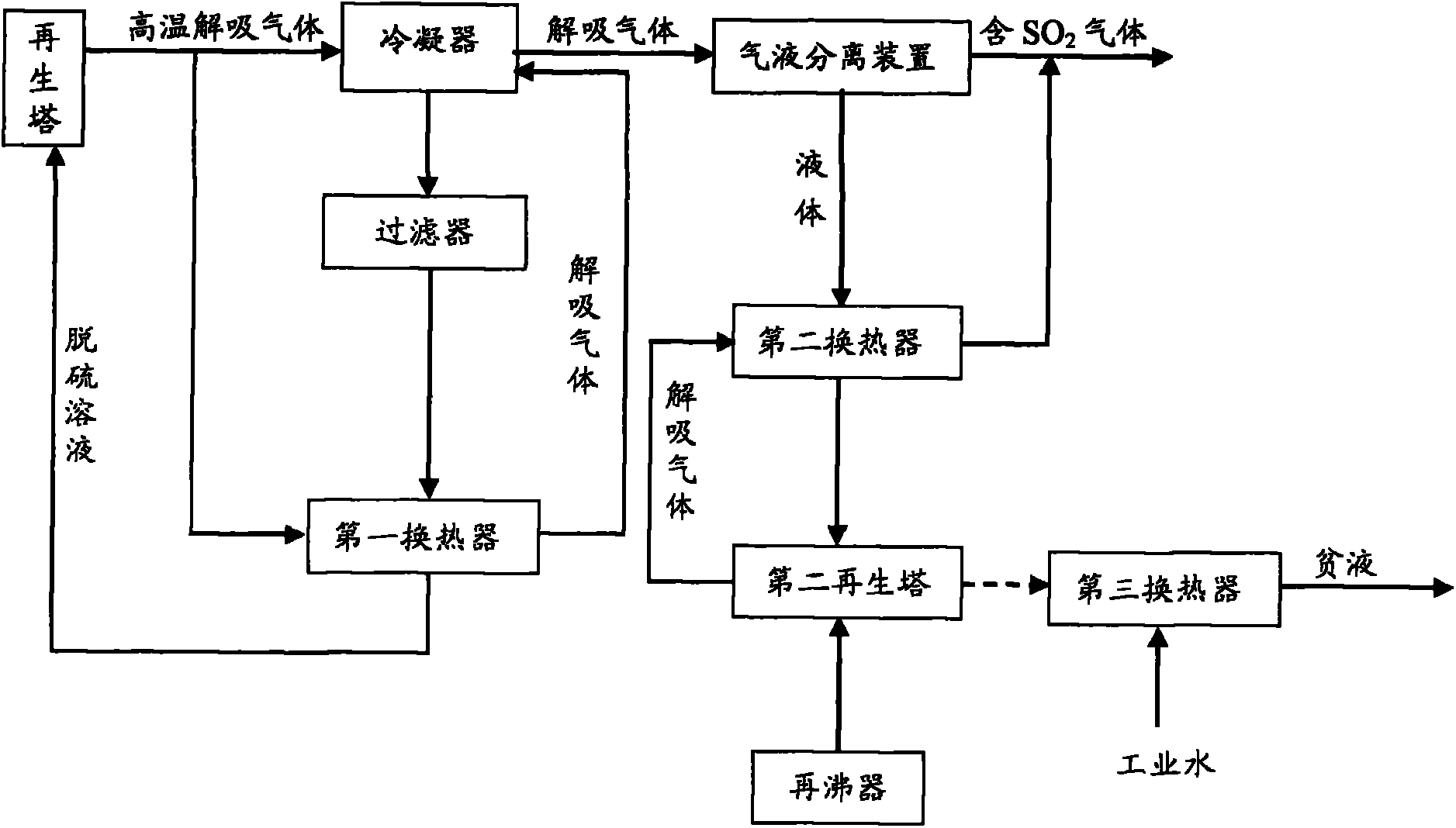
[0035] refer to figure 1 , in this embodiment, the high-temperature desorption gas desorbed from the regeneration tower is divided into two paths, and one path of desorption gas is supplied to the condenser for multi-stage condensation to produce condensate and containing water vapor, sulfur dioxide gas and a small amount of desulfurization The desorbed gas of the agent. The condensate mainly contains desulfurizer, some water and impurities, while a large amount of water still exists in the desorbed gas in the form of water vapor. Then, the condensate is supplied to a filter to be filtered to remove impurities, thereby obtaining a condensate mainly including a desulfurizing agent and a part of water (ie, as a desulfurization solution). At the same time, another desorbed gas is supplied to the first heat exchanger to exchange heat with the condensate supplied to the first heat exchanger, so that the temperature of the condensate rises to about 50°C-65°C, so that the filtered c...

Embodiment 2

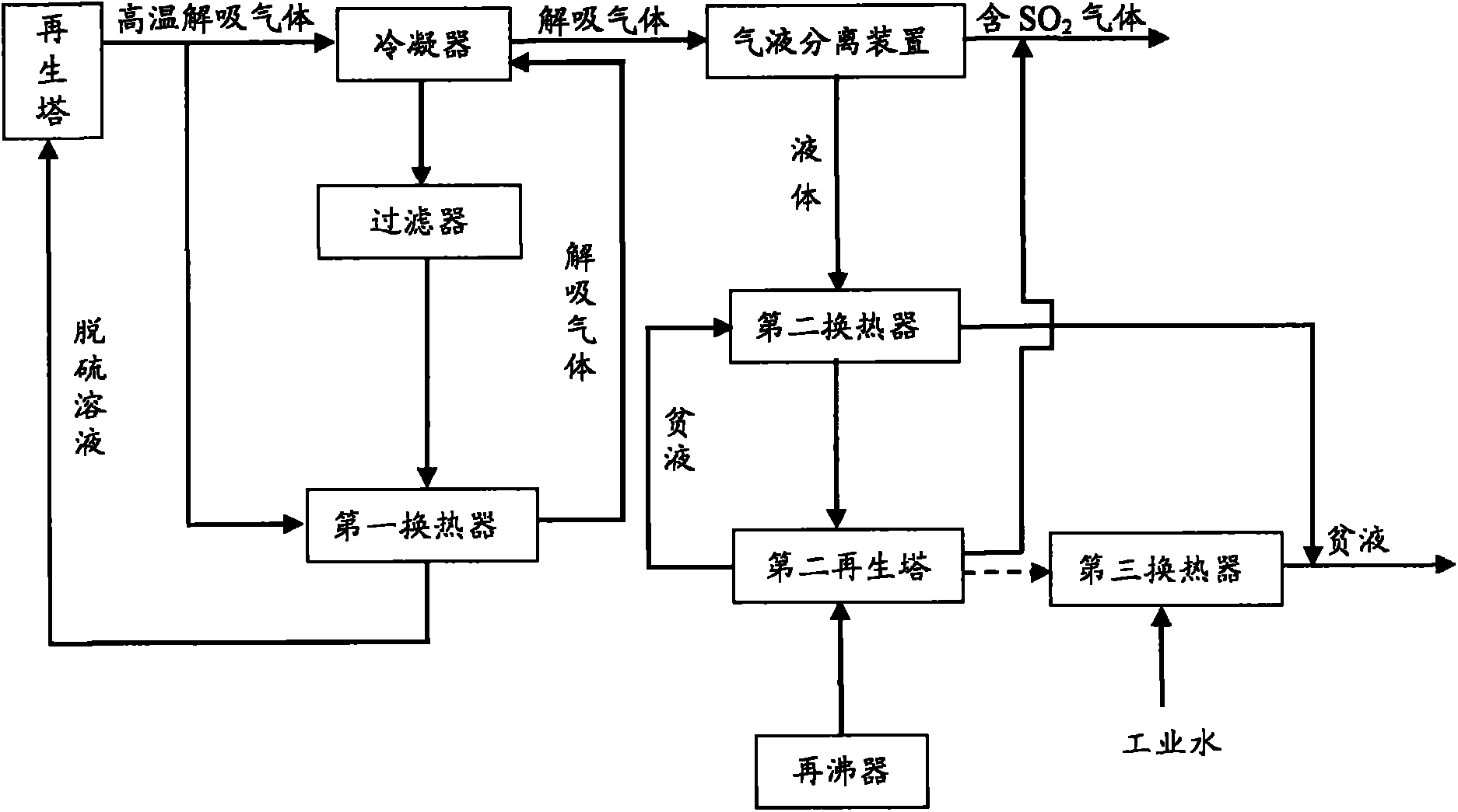
[0039] refer to figure 2 , in this embodiment, a part of the lean liquid produced in the second regeneration tower can be supplied to the second heat exchanger to exchange heat with the liquid produced after gas-liquid separation, and then the heat-exchanged liquid Part of the cooling lean liquid is discharged; at the same time, the desorption gas mainly containing sulfur dioxide produced in the second regeneration tower and containing high-purity SO 2 The gas is supplied to the acid system or stored together, except that the process steps of this embodiment are the same as those of Example 1. In addition, optionally, the remaining part of the lean liquid produced in the second regeneration tower is supplied to the third heat exchanger for heat exchange with industrial water, and then the part of the cooled lean liquid that undergoes heat exchange is supplied to the washing water system.

Embodiment 3

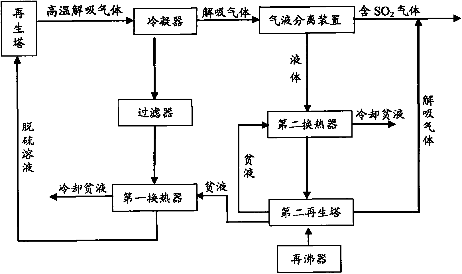
[0041] refer to image 3 , In this embodiment, the high-temperature desorption gas desorbed from the regeneration tower is supplied to the condenser for multi-stage condensation to produce condensate and desorption gas mainly containing water vapor, sulfur dioxide gas and a small amount of desulfurization agent. The condensate mainly contains desulfurizer, some water and impurities, while a large amount of water still exists in the desorbed gas in the form of water vapor. Then, the condensate is supplied to a filter to be filtered to remove impurities, thereby obtaining a condensate mainly including a desulfurizing agent and a part of water (ie, as a desulfurization solution). Then, the condensate is exchanged in the first heat exchanger, so that the temperature of the condensate is raised to 50° C. to 65° C., and then the heated condensate is returned to the regeneration tower.

[0042] In addition, the generated desorbed gas is supplied to a gas-liquid separator for gas-liq...


PUM


Abstract

The invention provides a method for dewatering desorption gas for flue gas desulfurization and recycling condensate. The method comprises the following steps: supplying the desorption gas desorbed from a regeneration tower to a condenser for multistage condensation so as to generate the condensate containing a desulfurizer, water and impurities and the desorption gas containing water vapor, sulfur dioxide gas and a desulfurizer; supplying the condensate to a filter for filtration so as to remove the impurities, thus obtaining a desulfurization solution containing the desulfurizer and the water; carrying out heat exchange on the desulfurization solution in a heat exchanger, and then returning the heated desulfurization solution to the regeneration tower; and supplying the generated desorption gas to a gas-liquid separator for gas-liquid separation so as to generate a liquid and gas containing sulfur dioxide. The process provided by the invention has the beneficial effects of effectively maintaining water quantity balance of a desulfurization system, maximally lowering the loss of sulfur dioxide and further reducing the energy consumption of a desorption system.

Description

technical field [0001] The invention relates to a method for removing water and reusing condensate in flue gas desulfurization and desorption gas, in particular to a method for dehydrating desorption gas and reusing condensate to reduce desorption energy consumption and maintain the concentration of desulfurization solution in the desulfurization system craft. Background technique [0002] Since sulfur dioxide seriously pollutes the environment, it is necessary to use a desulfurization solution containing a desulfurizer to absorb sulfur dioxide, and then to desorb the desulfurization solution rich in sulfur dioxide, so that the desulfurization solution desorbed from sulfur dioxide can be reused. Sintering flue gas containing water vapor, sulfur dioxide and a part of desulfurization agent. Traditionally, the desorption gas contains a large amount of water vapor, and the discharged desorption gas is condensed. On the one hand, the desorption gas mainly containing sulfur dioxi...

Claims


Application Information

Patent Timeline
Patent Type & Authority Applications(China)
IPC IPC(8): B01D53/14C01B17/56B01D5/00
Inventor 邱正秋任毅罗强罗义文
Owner PANZHIHUA IRON AND STEEL
Why Eureka
Try Eureka