Laser welding fixture for square battery module

A laser welding jig and battery module technology, applied in laser welding equipment, welding equipment, welding equipment, etc., can solve the problems of high heat generation, low efficiency, poor batch stability, etc., and achieve high welding success rate and easy operation quick effect

Active Publication Date: 2012-01-25
HEFEI GUOXUAN HIGH TECH POWER ENERGY
View PDF9 Cites 12 Cited by
  • Summary
  • Abstract
  • Description
  • Claims
  • Application Information

AI Technical Summary

Problems solved by technology

Although the existing double-needle spot welding equipment has low investment cost and simple operation, the welding quality is average, the penetration depth is small, the speed is slow, and the heat generation is large.
In addition, with the improvement of the power battery rate performance, the required discharge current is large, and the traditional copper-nickel composite board can no longer meet the needs of the large load current. It must be replaced by a red copper board, and the welding of the red copper board by the double-pin spot welding equipment poor effect
The quality of laser welding is good, the speed is fast, the depth of penetration is large, and the degree of automation is high. However, at present, laser welding of battery modules and copper connection plates can only be done manually, with low efficiency and poor batch stability.

Method used


Image

  • Laser welding fixture for square battery module
  • Laser welding fixture for square battery module
  • Laser welding fixture for square battery module

Examples


Embodiment 1

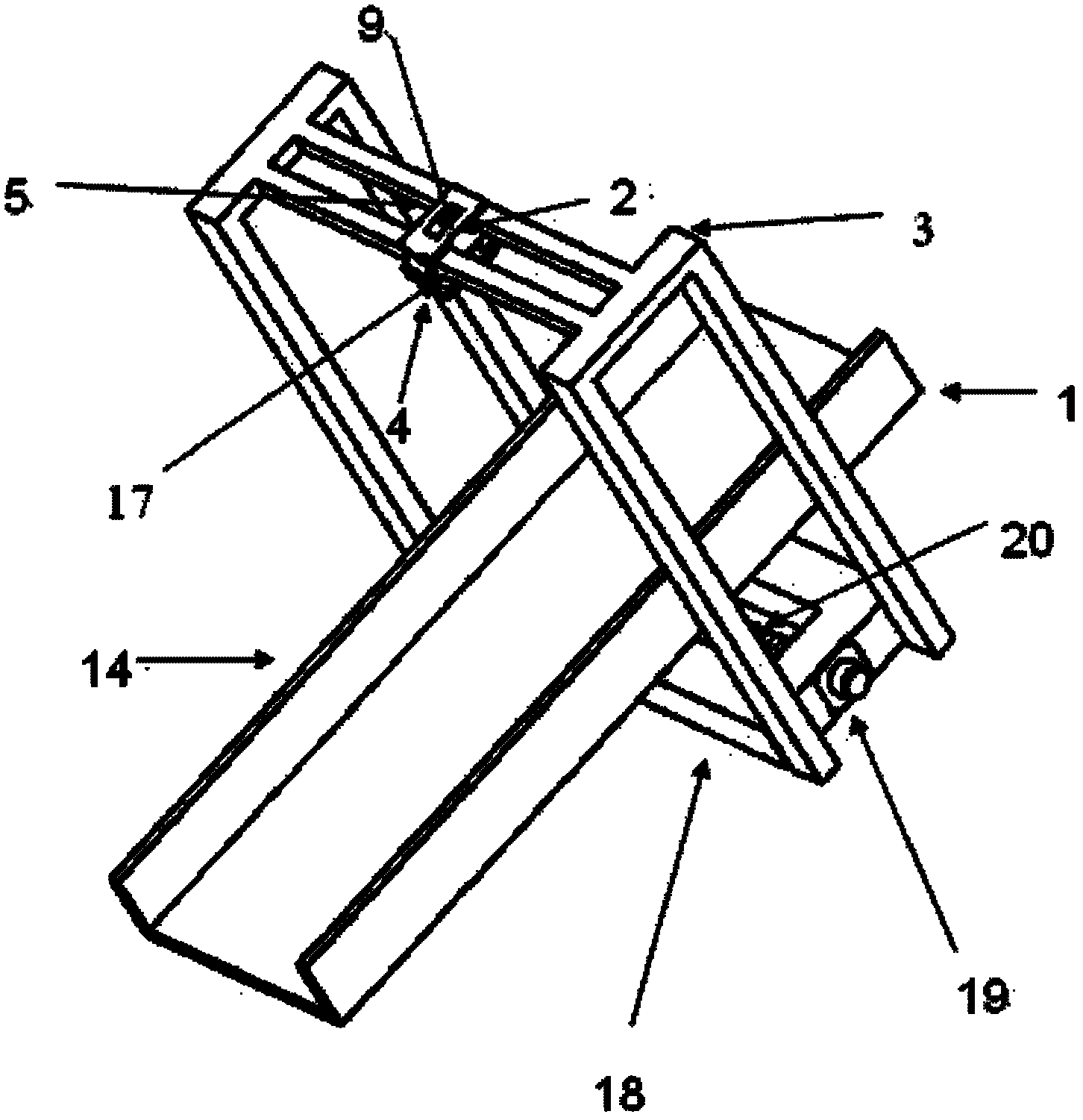
[0020] see figure 1 , is a preferred embodiment of the present invention, suitable for fiber output lasers. The fixture for welding the battery pack and the connecting piece mainly includes a workbench 1, a pressing mechanism 2 and an "H" type gantry support structure 3.

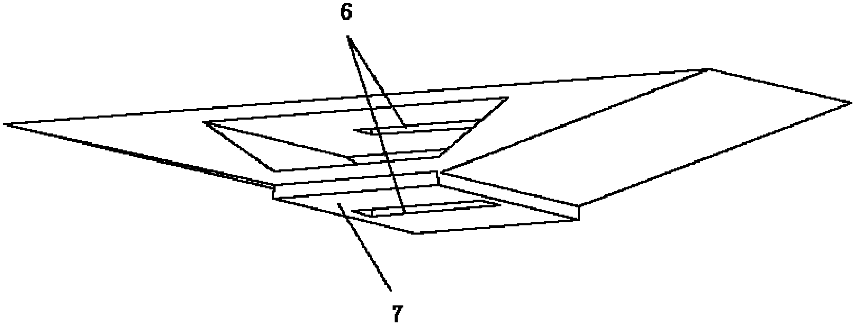
[0021] The pressing mechanism is fixed on the "H" type gantry support structure 3, which includes a pressing frame 4 and a cylinder driving device 5. The hold-down frame 4 is a steel structure with slits 6 (see figure 2 ). Both ends of the pressing frame 4 are respectively connected with the piston rod 17 of the cylinder driving device 5 . The bottom surface of the compression frame 4 has a rubber block 7 containing a slit 6 (see figure 2 ).

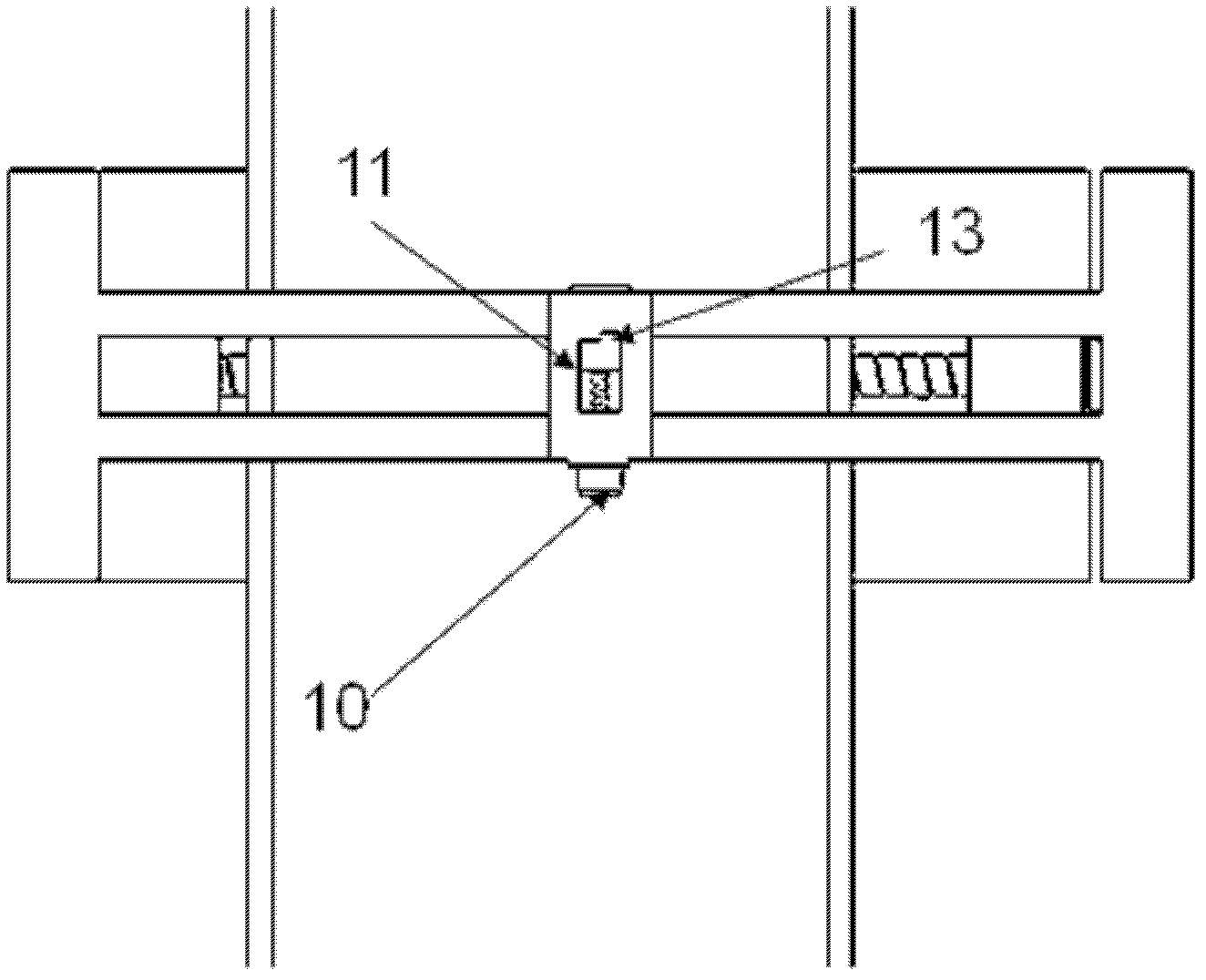
[0022] The "H" type gantry support frame 3 is fixed on both sides of the workbench 1, and it includes an "H" type gantry support frame 8 and a laser head driving device 9, and the driving device 9 is composed of a driving motor 10 and a screw rod 1...

Embodiment 2

[0027] see Figure 5-7 , this embodiment is applicable to a fixed optical path output laser. The fixture for welding the battery pack and the connecting piece mainly includes a workbench 1, a pressing mechanism 2 and an "H" type gantry support structure 3.

[0028] The pressing mechanism is fixed on the “H” type gantry support structure 3 , which includes a pressing frame 30 (see FIG. 6 ) and a cylinder driving device 5 . The pressing frame 30 is a steel structure with a slit 6 . Both ends of the pressing frame 30 are respectively connected with the piston rod 17 of the cylinder driving device 5 . A rubber block 7 containing a slit 6 is arranged on the bottom surface of the pressing frame 30 .

[0029] The "H" type gantry support frame is fixed on both sides of the workbench 1, and it includes an "H" type gantry support frame 21 and a pressing mechanism slide rail 22. A limit block 23 is fixed on the "H" type gantry support frame 21, which is used to limit the slidi...


PUM


Abstract

The invention relates to a laser welding fixture for a square battery module. The laser welding fixture comprises a worktable, a pressing mechanism and a supporting mechanism, wherein, the pressing mechanism is fixed on an 'H'-shaped gantry support structure and comprises a pressing frame and a cylinder drive unit; the 'H'-shaped gantry support structure is fixed at two sides of the worktable and comprises an 'H'-shaped gantry support frame and a laser head drive unit; and the worktable comprises an X-Y axis drive unit and a supporting platform. By adopting the structure, the laser welding fixture has the beneficial effects that a connection piece can be tightly contacted with a battery cover plate during the welding process, thus achieving high welding success rate; and in addition, by means of movable arrangement of the worktable, the whole battery module can be completely welded only by one-time setup, thus being simple, convenient and fast in operation.

Description

technical field [0001] The invention relates to a fixture, in particular to a square battery module laser welding fixture. Background technique [0002] In the current non-riveting method of assembling lithium-ion batteries into groups, it is necessary to use double-needle spot welding to weld the copper-nickel composite plate to the stainless steel pressure plate of the battery cover. Although the existing double-needle spot welding equipment has low investment cost and simple operation, the welding quality is average, the penetration depth is small, the speed is slow, and the heat generation is large. In addition, with the improvement of the power battery rate performance, the required discharge current is large, and the traditional copper-nickel composite board can no longer meet the needs of the large load current. It must be replaced by a red copper board, and the welding of the red copper board by the double-pin spot welding equipment poor effect. The quality o...

Claims


Application Information

Patent Timeline
Patent Type & Authority Applications(China)
IPC IPC(8): B23K37/04B23K26/08B23K26/20B23K26/21B23K26/70
Inventor 宫璐邵意志
Owner HEFEI GUOXUAN HIGH TECH POWER ENERGY
Why Eureka
Try Eureka