Four-electrode welding device for fiber splicer

A technology of optical fiber fusion splicing machine and welding device, which is applied in the direction of light guides, optics, optical components, etc., and can solve problems such as uneven heating of optical fibers and failure of fusion splicing

Pending Publication Date: 2017-11-24
NANJING JILONG OPTICAL COMM
View PDF2 Cites 2 Cited by
  • Summary
  • Abstract
  • Description
  • Claims
  • Application Information

AI Technical Summary

Problems solved by technology

[0003] However, for example, some applications of high-power fiber lasers require the fiber diameter to be over 1mm, and ordinary fusion splicing equipment will not be able to thermally fuse 200um optical fibers. The existing technologies for thermally melting large fiber diameters are mainly resistance wire or laser heating. diameter of the optical fiber, the dielectric properties of the optical fiber material can make the arc discharge region 3 bend around the optical fiber instead of wrapping the entire circumference of the optical fiber 2, such as figure 2 shown; but the above method may cause uneven heating of the fiber and lead to fusion splicing failure

Method used


Image

  • Four-electrode welding device for fiber splicer
  • Four-electrode welding device for fiber splicer
  • Four-electrode welding device for fiber splicer

Examples


Embodiment Construction

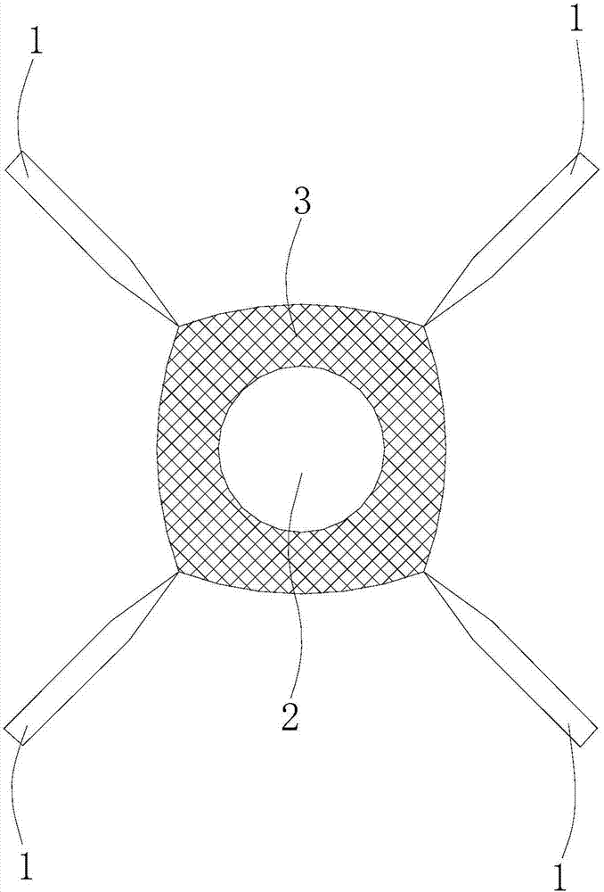
[0014] Such as image 3 shown

[0015] The electrode welding device includes four electrode rods 1, the four electrode rods 1 are arranged in a square, the center lines of the four electrode rods 1 are all in the same vertical plane, and the extension lines of the center lines of the four electrode rods 1 intersect at one point, each The tips of each electrode rod 1 point to this intersection point, the outer diameter of each electrode rod 1 is 2 mm, and the minimum distance between any two electrode rods 1 is 4 mm.

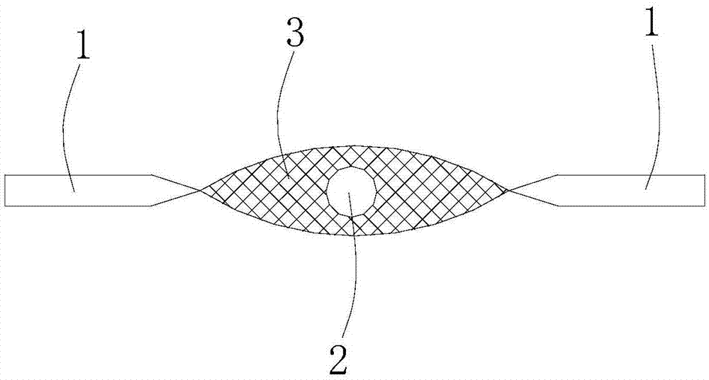
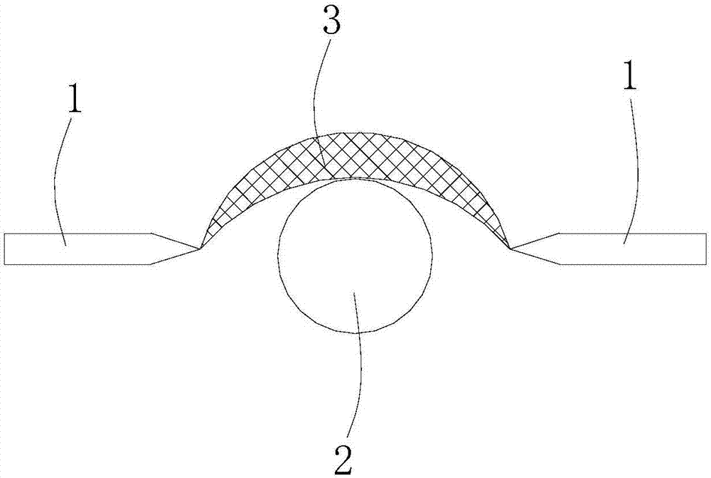
[0016] When in use, the four electrode rods 1 are energized, an arc discharge area 3 is generated between the tips of the four electrode rods 1 , and the end face of the large-diameter optical fiber 2 is placed in the arc discharge area 3 .

[0017] What has been described above is only one embodiment of the present invention. It should be pointed out that for those of ordinary skill in the art, some modifications and improvements can be made without departing f...


PUM


Abstract

The invention provides a four-electrode welding device for a fiber splicer; the four-electrode welding device comprises four electrode rods arranged in a rectangular form, center lines of the four electrode rods are coplanar, extension lines of the center lines of the four electrode rods intersect at a point, and the tips of all the electrode rods point to the point; after the four electrode rods are electrified, an arc discharge zone is formed among the tips of the four electrode rods. The arc discharge zone generated by the four-electrode welding device can splice a thick fiber or multiple fibers, and can withhold slight fluctuations from outside; the four-electrode welding device is disposed in partial or complete vacuum; compared with the prior art, the four-electrode welding device, with convection eliminated (or diminished) and an enhanced plasma field isothermal range provided, has the advantages that slight upward fluctuations are generated at the premise of rising of heat from plasm (under atmospheric pressure) and may destroy ionic paths among the electrodes, and the destroying may sway or extinguish plasma in air.

Description

technical field [0001] The invention relates to an electrode welding device, in particular to a four-electrode welding device for an optical fiber fusion splicer. Background technique [0002] The optical fiber fusion splicer uses two electrode rods 1 to generate a high-voltage arc to melt the sections of the two optical fibers. At the same time, it uses a high-precision motion mechanism to gently advance the two optical fibers into one. Most optical fibers have a diameter of 80um to 125um (not including the coating layer). Arc discharge region 3 melts the above-mentioned optical fiber 2 cross-section treatment situation as follows figure 1 shown. [0003] However, for example, some applications of high-power fiber lasers require the fiber diameter to be over 1mm, and ordinary fusion splicing equipment will not be able to thermally fuse 200um optical fibers. The existing technologies for thermally melting large fiber diameters are mainly resistance wire or laser heating. d...

Claims


Application Information

Patent Timeline
Patent Type & Authority Applications(China)
IPC IPC(8): G02B6/255
CPCG02B6/2551
Inventor 程飞吴超孙雅静
Owner NANJING JILONG OPTICAL COMM
Why Eureka
Try Eureka