Waste gas purifying method for textile printing and dyeing setting machine and complete equipment thereof

A waste gas purification, textile printing and dyeing technology, applied in the direction of chemical instruments and methods, combined devices, separation methods, etc., can solve the problems of not being able to make full use of the heat energy of high-temperature gas, not being able to meet the needs of environmental protection, and not being able to achieve complete separation, so as to avoid The effect of secondary pollution and tertiary pollution, high efficiency of dust removal and oil collection, and small footprint

Inactive Publication Date: 2012-01-25
扬州荣康空气净化设备厂
View PDF0 Cites 9 Cited by
  • Summary
  • Abstract
  • Description
  • Claims
  • Application Information

AI Technical Summary

Problems solved by technology

This method cannot achieve complete separation. The upper layer of water still contains a large amount of oil and dirt, and the filling of the lower layer will still cause soil environmental pollution. Therefore, this technology can no longer meet the needs of environmental protection.
In addition, because the exhaust gas is high-temperature gas, the existing technology cannot make full use of the heat energy in the high-temperature gas, which is not conducive to saving production.

Method used


Image

  • Waste gas purifying method for textile printing and dyeing setting machine and complete equipment thereof
  • Waste gas purifying method for textile printing and dyeing setting machine and complete equipment thereof
  • Waste gas purifying method for textile printing and dyeing setting machine and complete equipment thereof

Examples


Embodiment Construction

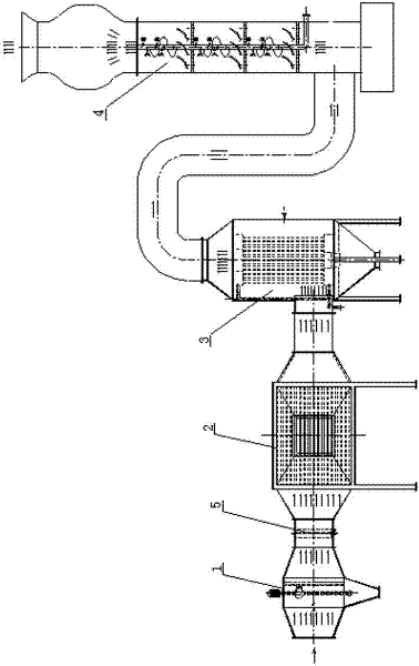
[0027] Such as figure 1 As shown, the present invention is mainly composed of a lint detachment device 1, a heat recovery device 2, an oil-gas separation device 3 and a gas purification device 4 connected in series through a connecting pipe, and between the lint detachment device 1 and the heat recovery device 2 Safety fire doors 5 are provided.

[0028] Its working principle is: after the lint in the exhaust gas is separated from the lint by the lint detachment device 1, after the heat energy recovery by the heat energy recovery device 2 and the oil removal by the oil-gas separation device 3, it will be purified by the gas purification device 4 and then discharged. If accidental flame occurs, the gas passage leading to the heat energy recovery device 2 is closed by the safety fire door 5 .

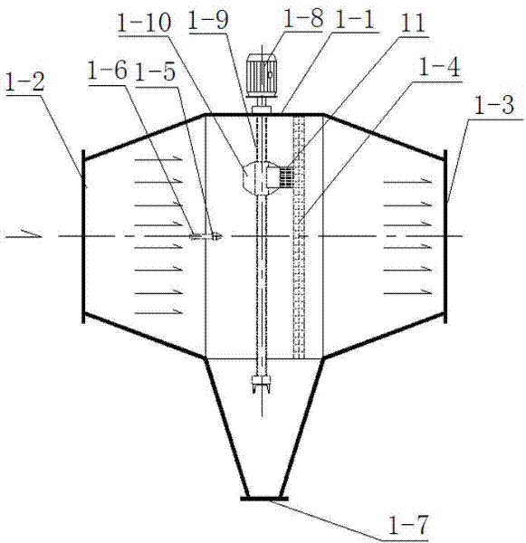
[0029] Such as figure 2 As shown, the lint removal device 1 is respectively provided with an air inlet 1-2 and an air outlet 1-3 at the left and right ends of the device housing 1-1, a...


PUM


Abstract

The invention discloses a waste gas purifying method for a textile printing and dyeing setting machine and complete equipment thereof, relates to the technical field of textile and also relates to the technical field of waste gas purification. After cotton velvet in waste gas is separated by a cotton velvet separation device, waste gas is subjected to heat energy recovery by a heat energy recovery device, is subjected to oil removal by an oil-gas separation device, is purified by a gas purification device and finally is discharged. The waste gas purifying method for the textile printing and dyeing setting machine and the complete equipment thereof has the excellent characteristics that the waste gas purifying method and the complete equipment thereof are simple and convenient to operate, have no hazard and are safe and reliable; the complete equipment has corrosion resistance and temperature resistance; the cost is saved; the occupied area is small; the service life is long; wastewater is recycled; the investment and the operation cost of the equipment are low; the efficiency of degreasing, removing dust and collecting oil is high; and the like. Therefore, the finally discharged gas meets the requirements of environmental-friendly discharge.

Description

technical field [0001] The invention relates to the technical field of textiles, and also relates to the technical field of waste gas purification. Background technique [0002] The exhaust gas emitted by the textile printing and dyeing sizing machine not only contains a lot of smoke and dust, but also contains polyphenylene organic matter, printing and dyeing auxiliaries, lint, oil and other components. Each sizing machine generally emits 150-250 mg / m of particulate matter 3 , soot 40-80mg / m 3 . With the increase of production, the oil, smoke and dust discharged are very harmful to human health and the environment, and the pollution problem caused by the exhaust gas emission of the setting machine has become more and more acute. The fume in the exhaust gas of the sizing machine comes from the chemical fiber oil in the cloth volatilized during the high-temperature sizing of the sizing machine and the chain oil lubricated by the sizing machine, including phosphate esters an...

Claims


Application Information

Patent Timeline
IPC IPC(8): D06C7/02B01D50/00B01D5/00B01D53/78B01D45/14
CPCY02P70/10
Inventor 汤荣康
Owner 扬州荣康空气净化设备厂
Why Eureka
Try Eureka