Low-power ventilating fan

A ventilation fan and low-power technology, applied in the direction of non-variable pumps, pump devices, machines/engines, etc., can solve the problems of high manufacturing cost, unsteady operation, uncertain rotation direction, etc., and achieve the effect that is beneficial to structural design

Inactive Publication Date: 2012-01-25
叶露微
View PDF5 Cites 32 Cited by
  • Summary
  • Abstract
  • Description
  • Claims
  • Application Information

AI Technical Summary

Problems solved by technology

However, if the traditional permanent magnet synchronous motor adopts complex structure and control, the manufacturing cost will be high, while if the simple structure and control are adopted, the direction of rotation will be uncertain, the starting torque will be low or the operation will not be stable, and the effect of the ventilation fan will be insufficient. good

Method used


Image

  • Low-power ventilating fan
  • Low-power ventilating fan
  • Low-power ventilating fan

Examples


Embodiment Construction

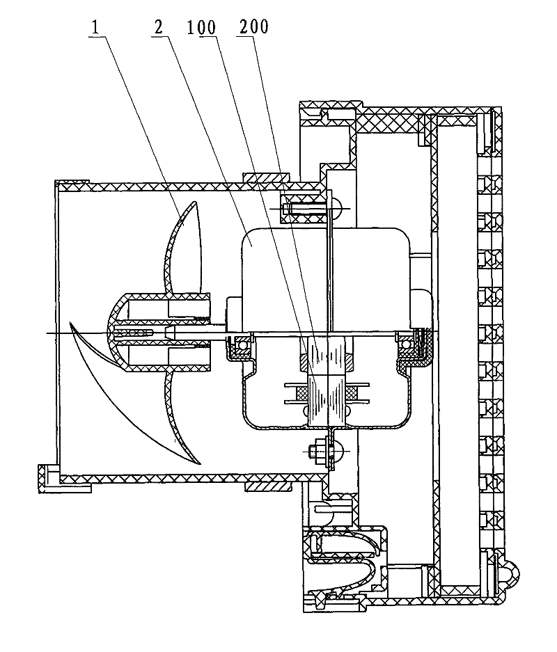
[0049] The basic mechanical structure of the ventilation fan in the embodiment of the present invention is as follows: figure 1 shown. This is a low-power axial flow ventilation fan, mainly including:

[0050] - motor 2 fixed to the casing;

[0051] ——An axial-flow impeller 1 directly connected to the output shaft of the motor and rotating counterclockwise has 4 blades; according to wind pressure requirements, the number of blades can also be 3, 5 or 6, but preferably not more than 8, And as odd as possible to reduce vibration noise. The impeller is injection molded with a diameter of 100mm. The maximum diameter of the impeller should not exceed 150mm, and the moment of inertia should be as small as possible to match the starting torque of the motor 2 which is still not too large;

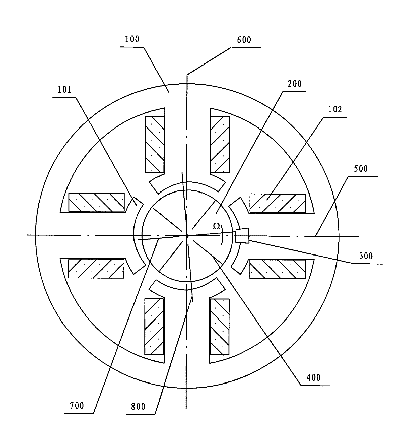
[0052] ——The motor 2 is an inner rotor motor, including a stator 100 and a permanent magnet rotor 200 .

[0053] The basic electromagnetic structure of the electric motor of the ventilating fa...


PUM


Abstract

The invention provides a low-power ventilating fan which comprises a minisize permanent magnet synchronous motor and an impeller which can be directly driven by the motor and can rotate according to a predetermined rotating direction, wherein the impeller is of an axial-flow type and manufactured in an injection moulding mode, the diameter of the impeller is not more than 150mm; the pole number of a motor stator is 4 or 6 or 8, the winding of the stator is connected to an alternating current power supply according to a specified winding direction; the pole number of a permanent magnet rotor is the same with that of the stator; air gap of each pole can be narrowed along the rotating direction, so that each pole axis of the rotor can deflect an acute angle along the rotating direction in the free state by taking the axis of one pole of the closest stator as a reference; a position sensor can detect the rotor at a set position on the circumference of the rotor, a control circuit can determine the direction of each polar permanent magnet flux and detect the power supply polarity by taking the position as a reference and the output of the sensor so as to determine the axis direction ofeach polar main flux of the stator; when the motor starts, a switch can connect the half wave of the power supply if the main flux axis direction and the permanent magnet flux axis direction are intersected and form the acute angle; or when the motor runs, the switch can connect the half wave of the power supply right now if the main flux axis direction is opposite to the permanent magnet flux axis direction or close to the opposite direction. The ventilating fan has better performance in the starting and running processes, while the cost is relatively low.

Description

technical field [0001] The invention relates to a low-power ventilating fan directly driven by a miniature permanent magnet synchronous motor, in particular to the cooperation of its mechanical structure, electromagnetic structure and control method. Background technique [0002] Ventilation fans are widely used and run for a long time, so there is an urgent need for low-cost manufacturing and energy-saving operation. Ventilation fans are still generally driven by asynchronous motors. Although the manufacturing cost is low, the efficiency is obviously low. Most ventilating fans usually do not need to be adjusted in speed. The prior art has discussed using a permanent magnet synchronous motor to drive, which can obviously save energy and have a small volume. However, if the traditional permanent magnet synchronous motor adopts complex structure and control, the manufacturing cost will be high, while if the simple structure and control are adopted, the direction of rotation w...

Claims


Application Information

Patent Timeline
Patent Type & Authority Applications(China)
IPC IPC(8): F04D25/08
Inventor 叶露微
Owner 叶露微
Why Eureka
Try Eureka