Bone graft capable of being directly implanted into intervertenral space and production tool thereof

A technology for making tools and intervertebral, which is applied in the field of forming molds for intervertebral bone grafting. It can solve the problems of inability to effectively support and maintain intervertebral height, loss of height of grafted bone blocks, and failure of fusion, so as to achieve good bone fusion and good bone quality. Conductivity, simple and convenient operation

Inactive Publication Date: 2012-02-01
李健
View PDF6 Cites 9 Cited by
  • Summary
  • Abstract
  • Description
  • Claims
  • Application Information

AI Technical Summary

Problems solved by technology

But there are also some shortcomings, such as: the commonly used carrier Cage + allograft bone/artificial bone implantation method often occurs such as: rejection, fusion cage sinking, displacement and compression of the dural sac, nerves and spinal cord Nerve compression, bone nonunion, infection, etc., may even cause the risk of blood-borne diseases; at the same time, these bones require a long time to grow in the crawling replacement mode, so it takes a long time to fuse, and because of the special carrier material, the cost Expensive, increasing the financial burden on patients
Another example: in the current method of autologous bone grains to suppress bone grafting,

Method used


Image

  • Bone graft capable of being directly implanted into intervertenral space and production tool thereof
  • Bone graft capable of being directly implanted into intervertenral space and production tool thereof
  • Bone graft capable of being directly implanted into intervertenral space and production tool thereof

Examples


Example Embodiment

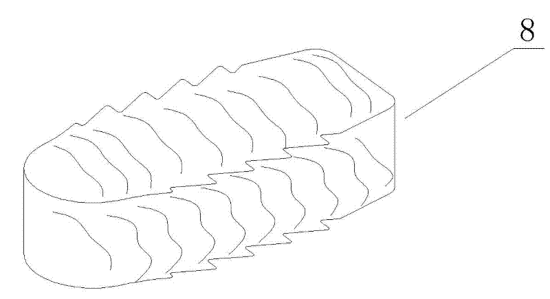
[0017] Such as figure 1 As shown, a bone graft block that can be directly implanted between the vertebrae, the bone graft block 8 is compacted into the required shape from the bone fragments obtained from intraoperative decompression by corresponding production tools. The bone fragments obtained by the decompression are compacted into the bone graft block 8 of the required shape by the corresponding production tools, and the bone graft block 8 can be directly implanted in the intervertebral space. The compressed bone graft block 8 is biomechanically determined It has a certain degree of resistance to pressure, can effectively support and maintain the height of the intervertebral, and is not easy to break, and has high safety. Moreover, the bone graft block 8 is autologous bone, so it has good osteoconductivity and osteoinductivity. After implantation in the intervertebral space The fusion time is short, the healing rate is high, and there is no rejection reaction. There is no ne...


PUM


Abstract

The invention provides a bone graft capable of being directly implanted into an intervertenral space. The bone graft is produced by compacting broken bone pieces obtained by pressure reduction in operations into a body of a required shape by a corresponding production tool, and can be directly implanted into an intervertenral space. The bone graft has certain compression resistance, can effectively support and maintain the intervertenral height, is not liable to break and has high safety. The bone graft does not need a fusing machine as a carrier, thus enlarging the contact area between the upper and lower end plate interfaces between the bone graft and a vertebral body, and being favorable for bone fusion. Moreover, the bone graft greatly reduces the operation cost, relieves patients of expensive treatment, and can be extensively applied to intervertenral bone graft fusion operations in hospitals. The invention also provides a production tool for producing the bone graft, the cavity depth of the production tool is set in proportion according to the thickness of the bone graft, spacing structures are arranged for limiting the depth of pressing a die block into a die cavity, and during compaction, the thickness of the bone graft can be obtained by filling broken bone pieces in the die cavity and compacting until the two spacing structures are in contact, so that the production tool is simple and convenient in operation and strong in practicability.

Description

Technical field [0001] The invention relates to a bone implant molding mold, in particular to a molding mold for intervertebral bone grafting. Background technique [0002] Many spinal surgery operations often require pedicle screw fixation and intervertebral bone graft fusion. There are many types of intervertebral fusion, which have a certain effect on promoting intervertebral fusion. However, there are some shortcomings, such as: the commonly used carrier Cage+ allograft bone / artificial bone implantation methods, such as rejection, fusion cage sinking, displacement and compression of the dural sac, nerves and spinal cord Nerve compression, bone non-union, infection, etc., and even the danger of causing blood-borne diseases; at the same time, these bones require a longer growth time in the alternative way of crawling, so it takes a long time to fuse, and because of the special carrier material, the cost Expensive, increasing the financial burden of patients. Another example: ...

Claims


Application Information

Patent Timeline
IPC IPC(8): A61F2/44
CPCA61F2/44A61F2002/30001
Inventor 李健余伟雄
Owner 李健
Why Eureka
Try Eureka