
Valve actuating mechanism on engine

A valve train and engine technology, applied in mechanical equipment, engine components, machines/engines, etc., can solve the problems of complex gear meshing and transmission, and achieve the effect of full inflation, large power and weight, and light weight

Inactive Publication Date: 2012-02-01
上海北星实业有限公司
View PDF5 Cites 1 Cited by
  • Summary
  • Abstract
  • Description
  • Claims
  • Application Information

AI Technical Summary

Problems solved by technology

Since the camshaft is driven by the crankshaft, a chain and a sprocket must be used to rotate the two as soon as the distance is opened. The structure is much more complicated than the gear meshing transmission of the lower camshaft.

Method used

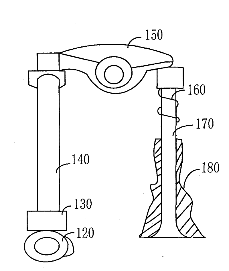
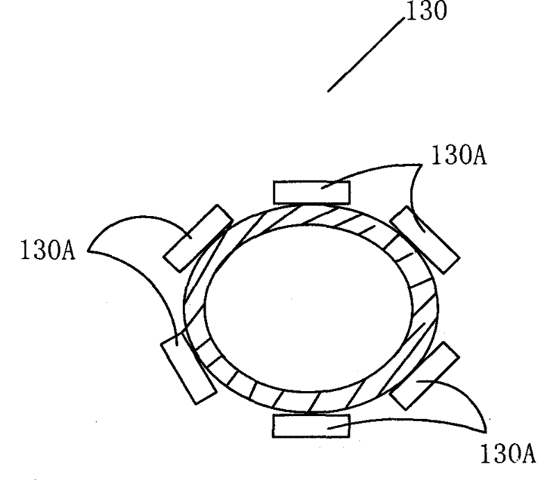

Image

  • Valve actuating mechanism on engine
  • Valve actuating mechanism on engine
  • Valve actuating mechanism on engine

Examples


Embodiment Construction

[0020] In order to describe the technical content, structural features, achieved goals and effects of the present invention in detail, the following will be described in detail in conjunction with the embodiments and accompanying drawings.

[0021] By common knowledge, we can know: engine engine can be divided into two-stroke engine and four-stroke engine, and two-stroke engine refers to the engine that piston moves two strokes and crankshaft completes one working cycle in the cylinder. A four-stroke engine refers to an engine in which the piston moves four strokes or the crankshaft turns two cylinders to complete one working cycle. Both of these engines can be driven by various materials.

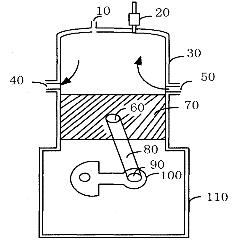
[0022] see figure 1 , in the prior art of the present invention, a structural schematic diagram of an engine, including:

[0023] Oil inlet 10, spark plug 20, cylinder 30, air outlet 40, air inlet 50, tip 60, piston 70, connecting rod 80, crank journal 90, crankshaft 100, crankcase 110. ...


PUM


Abstract

The invention discloses a valve actuating mechanism on an engine, which comprises a plurality of inlet valves, a plurality of exhaust valves, a first holding base, a second holding base, a first cam, a second cam, a first group of cylinders, a second group of cylinders and a push rod, wherein the inlet valves share the first cam, and the exhaust valves share the second cam. The valve actuating mechanism integrates the advantages of engine valves of four strokes and two strokes of the prior art and the existing art, and has the advantages of light weight, full air inflation, more complete ventilation as well as convenience and larger power and weight because the size of the radial engine is compact.

Description

technical field [0001] The invention relates to the field of engines, more specifically, to a valve mechanism on the engine. Background technique [0002] As we all know, the valve mechanism of the engine is a mechanism that ensures that the engine regularly fills the cylinder with fresh combustible gas mixture during operation, and discharges the exhaust gas after combustion from the cylinder in time. It is composed of intake valve, exhaust valve, valve lifter, tappet, rocker arm, camshaft, etc. Among them, the camshaft is also called peach shaft or eccentric shaft because of its cross-sectional shape similar to a peach. The driver is specially designed to drive the valve to open and close on time. The structure of the camshaft of the engine is similar, the main difference lies in the installation position, the number and shape and size of the cams are not the same, especially the installation position of the camshaft is listed as an important symbol to distinguish the str...

Claims


Application Information

Patent Timeline
Patent Type & Authority Applications(China)
IPC IPC(8): F01L1/06F01L1/14
Inventor 唐纳德陈妍
Owner 上海北星实业有限公司
Learn More