Floor type air conditioner

An air conditioner, floor-standing technology, applied in air conditioning systems, heating methods, space heating and ventilation, etc., can solve the problems of poor heat exchange effect and large gas flow resistance, achieve small airflow resistance, improve heat exchange effect, The effect of improving efficiency

Inactive Publication Date: 2012-02-01
GREE ELECTRIC APPLIANCES INC OF ZHUHAI
View PDF6 Cites 0 Cited by
  • Summary
  • Abstract
  • Description
  • Claims
  • Application Information

AI Technical Summary

Problems solved by technology

[0003] However, in the two methods currently used, since the airflow entering and exiting the evaporator is inclined to the

Method used


Image

  • Floor type air conditioner
  • Floor type air conditioner
  • Floor type air conditioner

Examples


Example Embodiment

[0026] The embodiments of the present invention will be described in detail below in conjunction with the drawings:

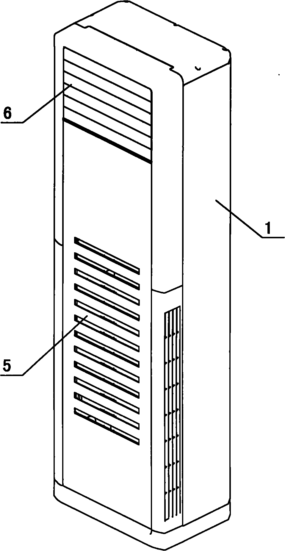
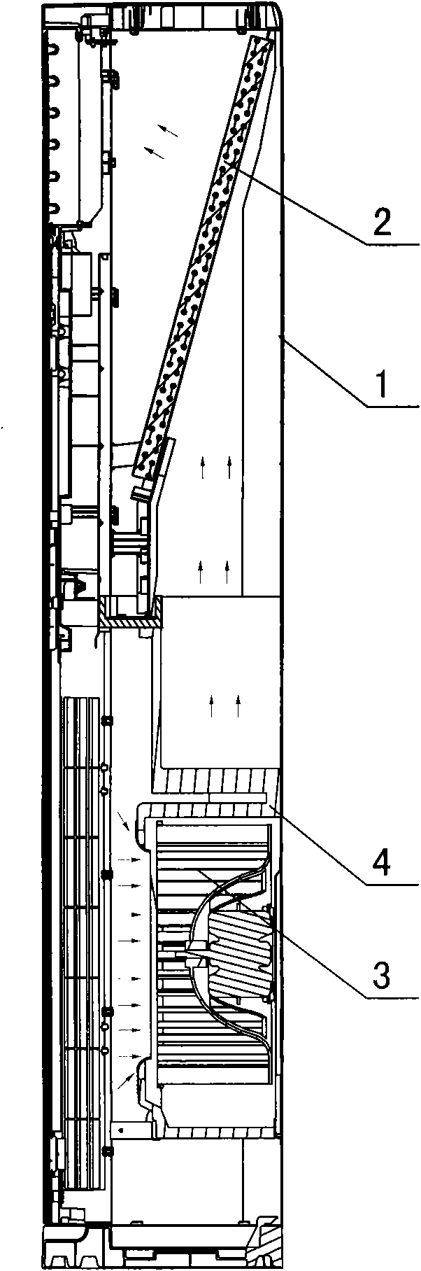
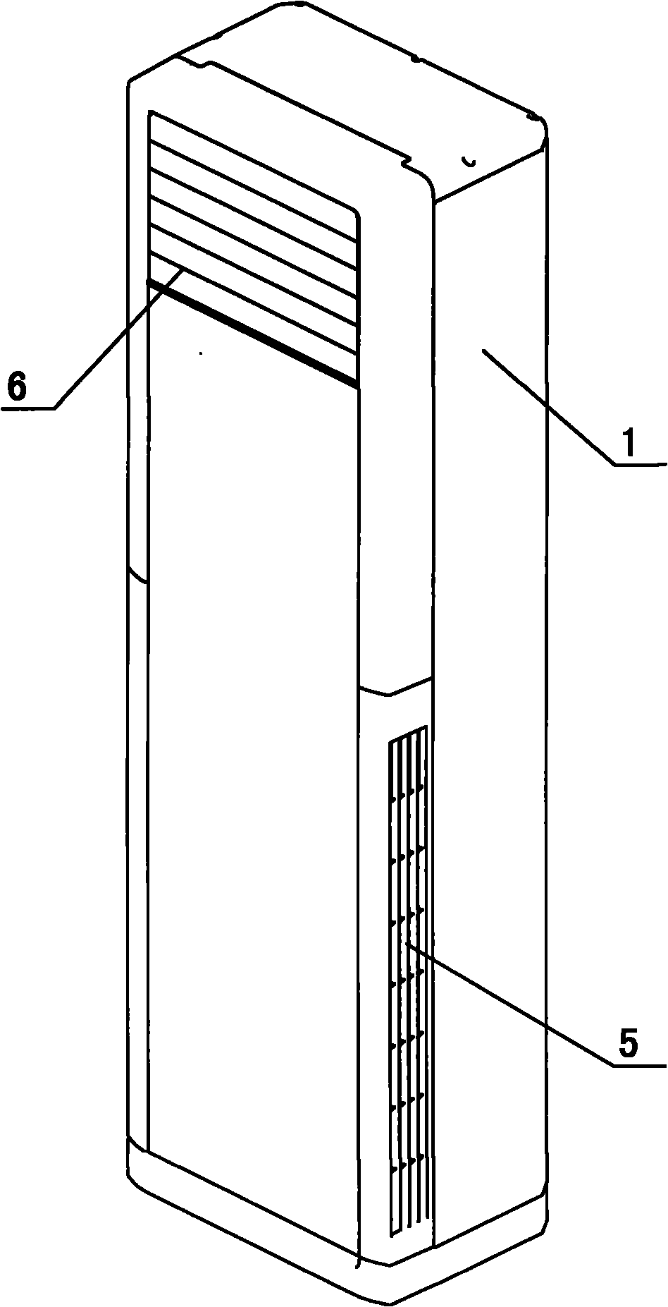
[0027] Such as Figure 2 to Figure 6 As shown, a floor-standing air conditioner includes a housing 1, in which a volute 4 and an evaporator 2 are provided, and a centrifugal fan 3 is provided in the volute 4; the evaporator 2 is upright and its The main body is perpendicular to the axis of the aforementioned centrifugal fan 3.

[0028] Wherein, the housing 1 is provided with an air inlet 5 and an air outlet 6. The air outlet 6 and the air inlet 5 are respectively located at the upper and lower parts of the housing 1, and the cooling channel between the air inlet 5 and the air outlet 6 is the evaporator 2. It is arranged on the cooling air duct and close to one end of the air inlet 5, the air outlet 6 is arranged directly in front of the casing 1, and the air inlet 5 is arranged on the left and right sides of the casing 1.

[0029] Between the evaporator 2 and the ce...


PUM


Abstract

The invention discloses a floor type air conditioner which comprises a shell, a volute and an evaporator are arranged in the shell, a centrifugal fan blade is arranged in the volute, the evaporator is arranged vertically and the main body of the evaporator is vertical to the axis of the centrifugal fan blade. The floor type air conditioner has the advantages of small air flowing resistance and good heat exchange effect.

Description

technical field [0001] The invention belongs to the field of air conditioners, and in particular relates to a floor-standing air conditioner. Background technique [0002] Ordinary split floor air conditioners such as figure 1 , figure 2 As shown, generally the air inlet 5 and the air outlet 6 are respectively arranged on the lower part and the upper part of the housing 1, and the air inlet 5 and the air outlet 6 are located directly in front of the housing 1, and the volute 4 and the centrifugal fan 3 are arranged In the lower part of the inner cavity of the air conditioner, the evaporator 2 is arranged on the upper part of the inner cavity of the air conditioner and placed obliquely, and the air duct system at the lower part blows air to the upper evaporator 2 to achieve the purpose of rapid heat exchange. There are also a small number of floor-standing air conditioners that set the motor, volute and centrifugal fan blades on the upper part of the air conditioner inner ...

Claims


Application Information

Patent Timeline
IPC IPC(8): F24F3/00F24F13/20F24F13/30F24F13/00
Inventor 张辉陈绍林孟宪运刘北泉王朝新
Owner GREE ELECTRIC APPLIANCES INC OF ZHUHAI
Why Eureka
Try Eureka