
Method of fabricating pattern

A manufacturing method and pattern technology, which can be applied in printed circuit manufacturing, cable/conductor manufacturing, photoplate-making process of patterned surface, etc., can solve problems such as low laser absorption rate, multi-light energy pattern width increase, etc. Absorption rate, laser absorption rate improvement, thermal diffusion reduction effect

Inactive Publication Date: 2012-02-01
KOREA ADVANCED INST OF SCI & TECH
View PDF4 Cites 8 Cited by
  • Summary
  • Abstract
  • Description
  • Claims
  • Application Information

AI Technical Summary

Problems solved by technology

However, since such inks are different from nanoparticle inks in that they do not contain metal particles, they are transparent and have a low laser absorption rate. Therefore, the problems of requiring more light energy and increasing the pattern width also occur when patterning is produced.

Method used


Image

  • Method of fabricating pattern
  • Method of fabricating pattern
  • Method of fabricating pattern

Examples


Embodiment Construction

[0054] Specific embodiments of the present invention will be described in detail below in conjunction with the accompanying drawings. However, the accompanying drawings are only used to better explain the contents of the present invention, and the scope of the present invention is not limited to the scope of the accompanying drawings, which should be easily understood by those skilled in the art. The advantages, features and implementation methods of the present invention will be very clear with reference to the accompanying drawings and the following detailed description. The same reference signs denote the same constituent elements throughout the specification. Marangony flow and hydrodynamic flow are necessary and will continue to be mentioned to explain the problems existing in the existing pattern manufacturing method and the effect of the present invention. However, marangony flow and hydrodynamic flow are explained together after the introduction of each claim.

[005...


PUM

PropertyMeasurementUnit
sizeaaaaaaaaaa
thicknessaaaaaaaaaa
thicknessaaaaaaaaaa

Abstract

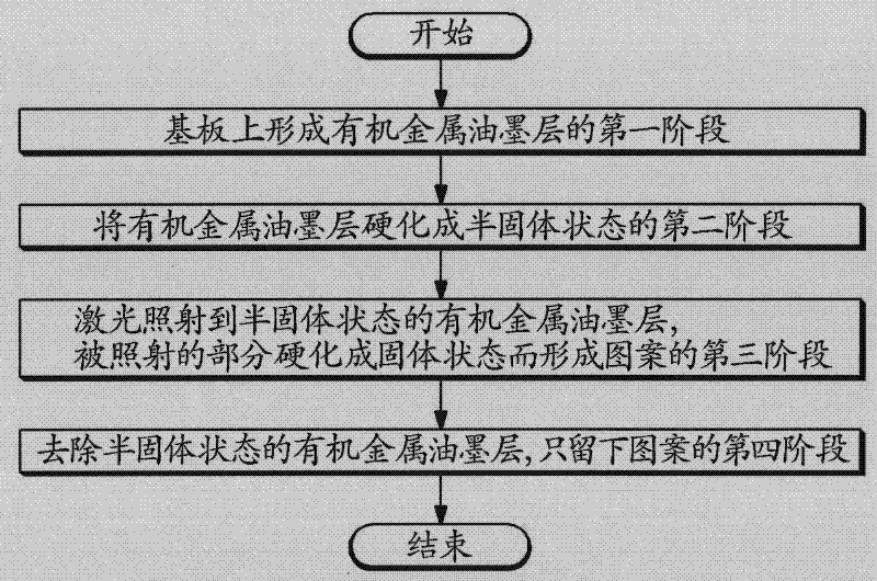
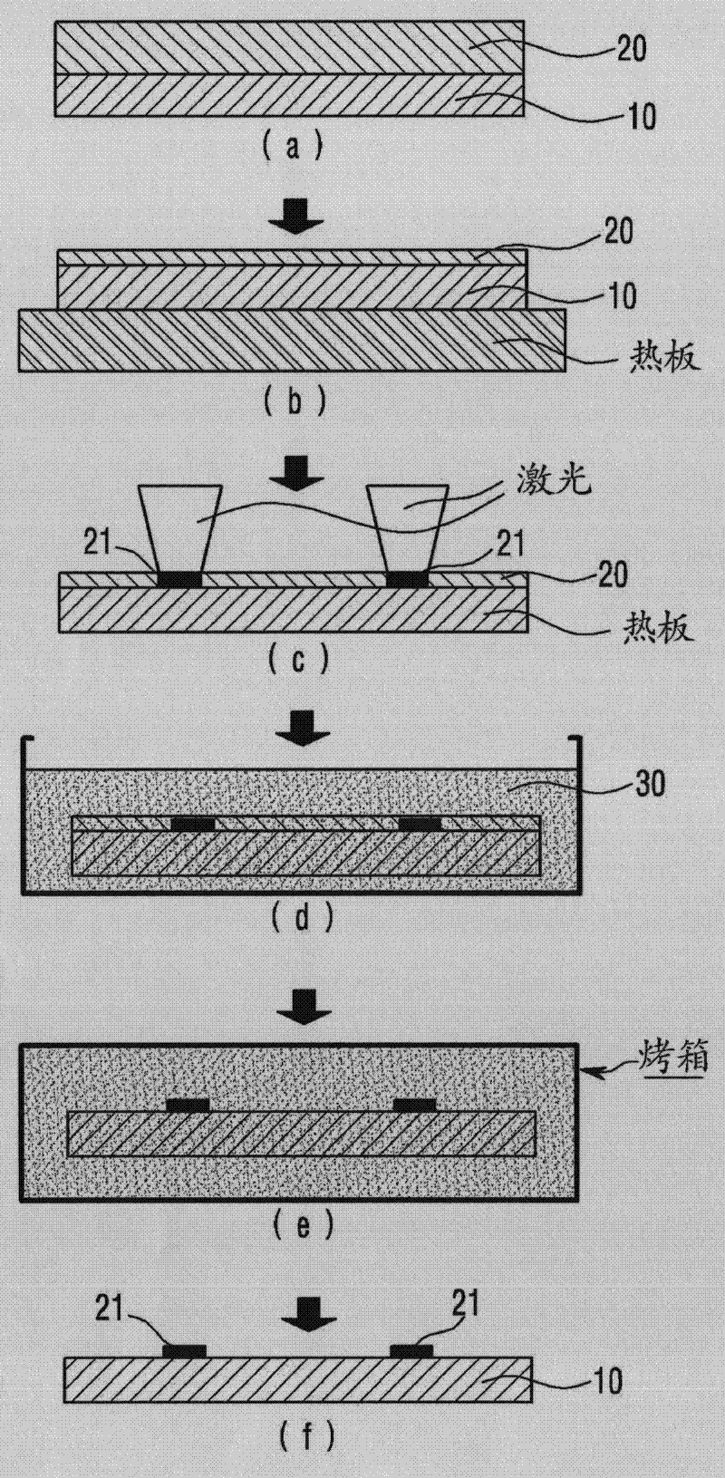
Disclosed is a method of fabricating a pattern, and more particularly is a method of fabricating a pattern by using laser. The method includes: a first step of forming an organometallic ink layer 20 on a substrate; a second step of curing the organometallic ink layer 20 into a semi-solid state; a third step of forming a pattern by irradiating laser onto the semi-solid organometallic ink layer 20, so that the irradiated portion of the organometallic ink layer 20 is changed into a solid state; and a fourth step of leaving only the pattern by removing the semi-solid organometallic ink layer 20.

Description

technical field [0001] The invention relates to a pattern manufacturing method, in particular, a method for manufacturing patterns by using laser light. Background technique [0002] Recently, the optical industry, display industry, semiconductor industry, and bioengineering industry have higher and higher requirements for thin film and high performance products. To comply with these requirements, the wiring or functional film layers that make up each component should be formed into smaller and more uniform patterns. Therefore, the manufacturing method of fine pattern is the basic technology of these industries. [0003] Conventionally, there have been many studies on the LDW method using nanoparticle ink as a non-exposed method of producing fine patterns. [0004] However, when nanoparticle inks with a size of tens of nanometers are directly irradiated with laser to form a pattern, it takes a long time for pattern formation due to a large amount of solvent and high temper...

Claims


Application Information

Patent Timeline
Patent Type & Authority Applications(China)
IPC IPC(8): G03F7/00H01B13/00H01L21/288H01L21/768
CPCH05K2203/121H05K2203/013H05K1/097H05K3/105H05K2201/0257H05K2203/107H05K3/1283G03F7/2018H01L21/0275H01L21/2683
Inventor 梁民阳康凤哲
Owner KOREA ADVANCED INST OF SCI & TECH
Learn More