
Novel LTCC (Low Temperature Co-Fired Ceramic) duplexer used for RFID (Radio Frequency Identification Devices) 2.4G

A duplexer and process technology, applied in the direction of impedance network, electrical components, multi-terminal pair network, etc., can solve the problems of increasing circuit board area, complex process, high manufacturing cost, etc.

Inactive Publication Date: 2012-02-01
SHANGHAI JIAOTAI INFORMATION TECH
View PDF3 Cites 11 Cited by
  • Summary
  • Abstract
  • Description
  • Claims
  • Application Information

AI Technical Summary

Problems solved by technology

[0004] After searching the literature of the prior art, it was found that Chinese patent 2292330Y proposed a duplexer prototype capable of suppressing the loss of multiple frequency band signals transmitted along the side of the high-frequency band-pass filter and the side of the low-frequency band-pass filter, from which It can be seen from the circuit prototype that the circuit components introduced in the patent are microstrip lines and discrete components, which cause the size of the components to be too large, which is not conducive to the miniaturization of the duplexer; Chinese patent 101018070A proposes a It can be seen from the simulation results given later that although the duplexer can meet the requirements of high isolation, the insertion loss is relatively large, and the process is complicated and the manufacturing cost is high. This kind of circuit prototype cannot be widely used in practice, and can only provide a theoretical reference; in addition, US Patent 0058063 uses many ground planes to separate circuit components, although this effectively blocks the connection between circuit components. Mutual coupling and parasitic effects, but on the other hand, it also increases the area of ​​the circuit board, which is undoubtedly unable to meet the requirements of miniaturization

Method used


Image

  • Novel LTCC (Low Temperature Co-Fired Ceramic) duplexer used for RFID (Radio Frequency Identification Devices) 2.4G
  • Novel LTCC (Low Temperature Co-Fired Ceramic) duplexer used for RFID (Radio Frequency Identification Devices) 2.4G
  • Novel LTCC (Low Temperature Co-Fired Ceramic) duplexer used for RFID (Radio Frequency Identification Devices) 2.4G

Examples


example 1

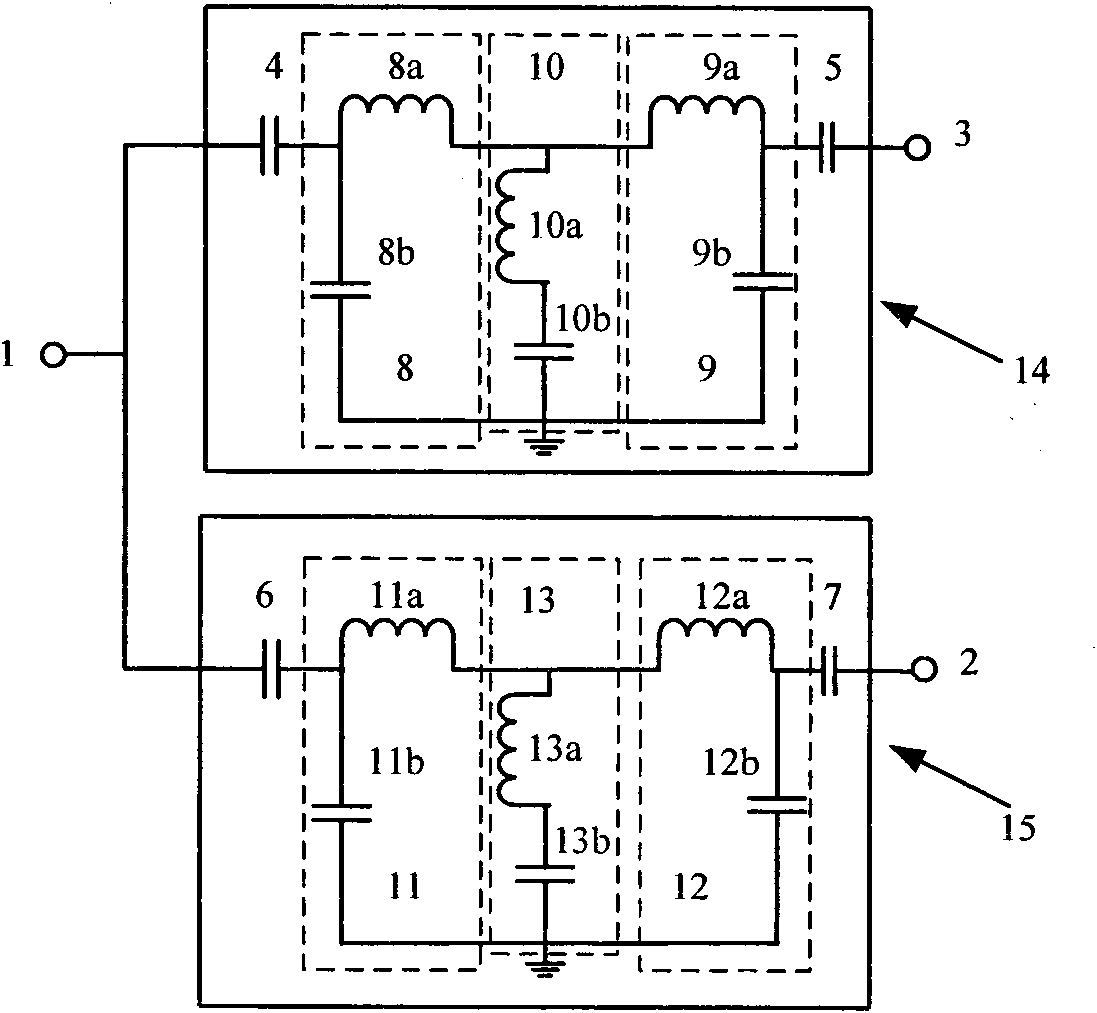
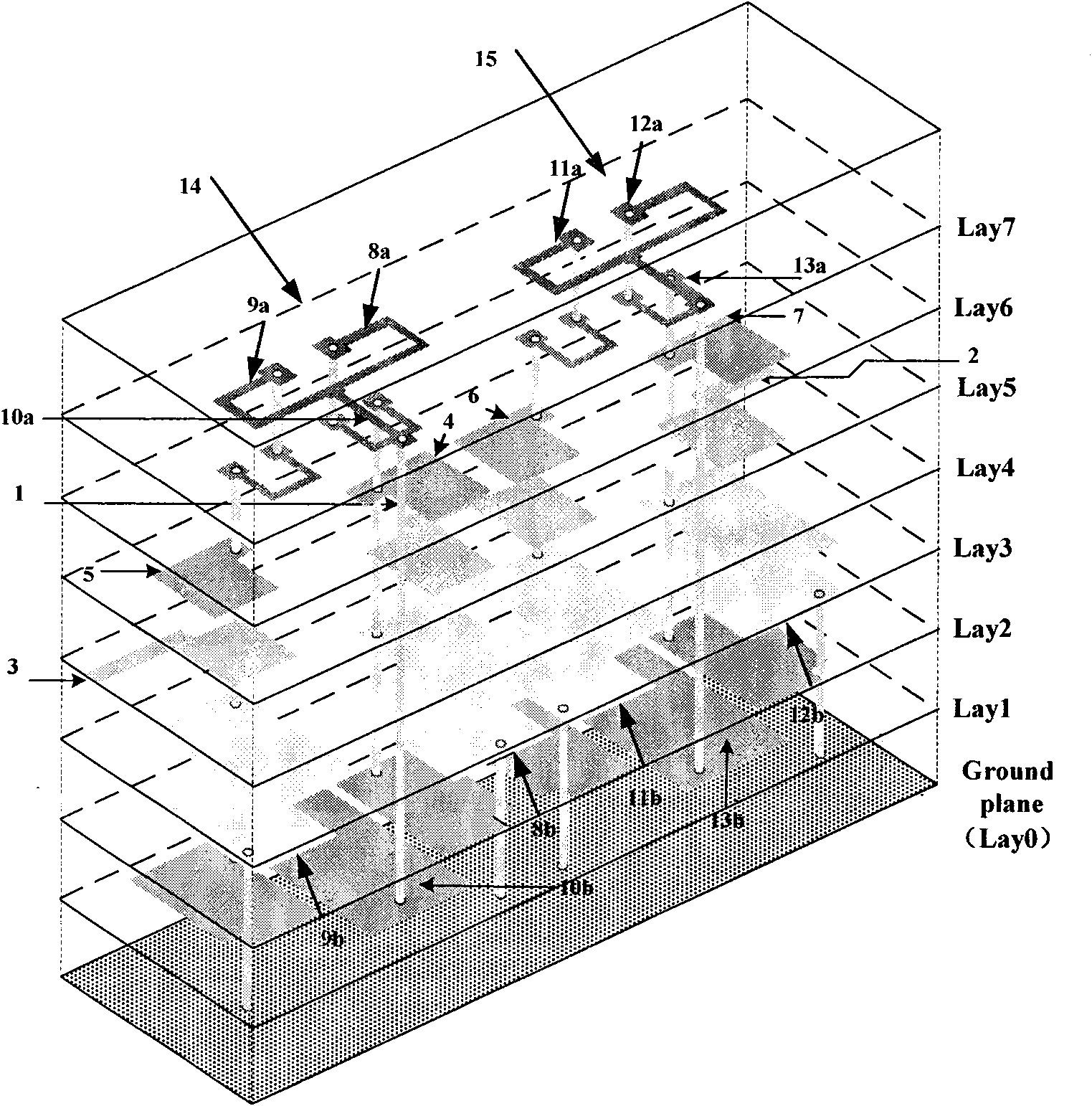
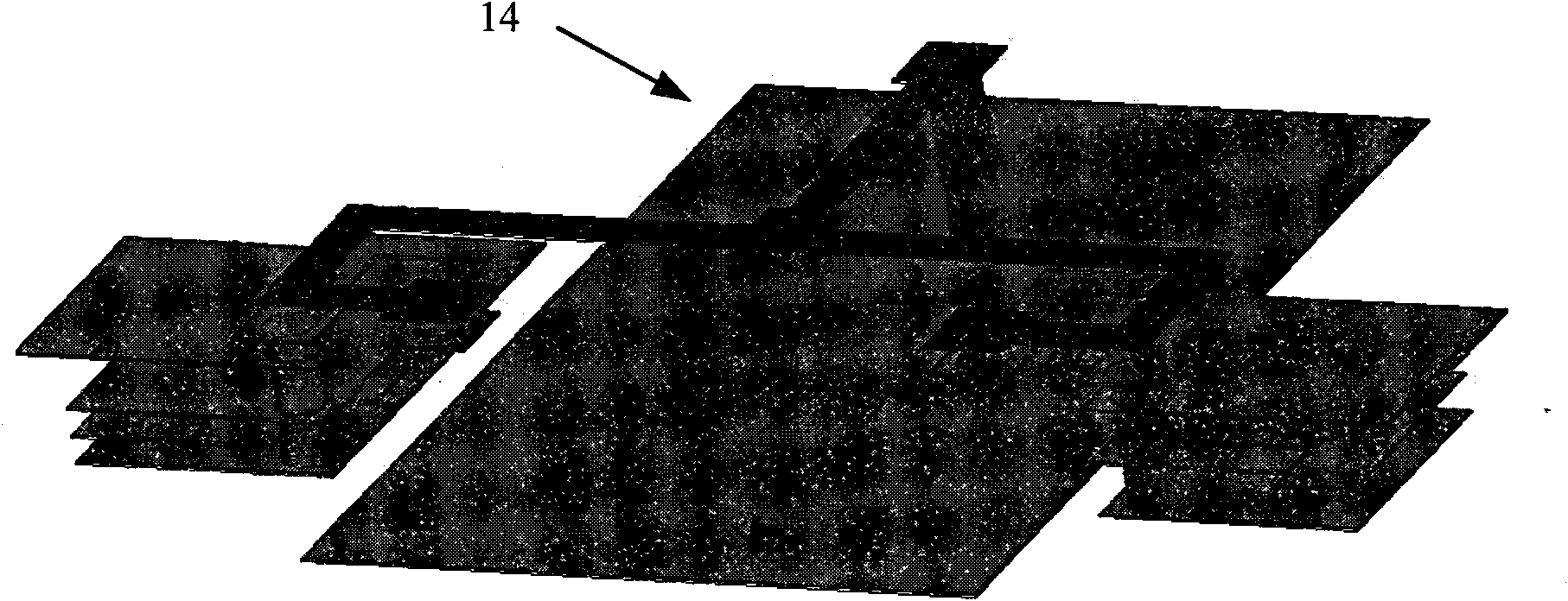
[0026] figure 2 Shown is this example based on figure 1Schematic diagram of the duplexer layout. The specific parameters of its instantiation are: the relative dielectric constant of the LTCC material used is 5.9, a total of seven layers of dielectric, each layer of dielectric thickness is 0.096mm, the dielectric loss tangent angle is 0.0015, the metal material is silver, and the thickness of each layer of metal is 0.01 mm, the width of all lines to realize the inductance is 0.15mm, the width of the square pad used is 0.235mm, the diameter of the metallized via hole is 0.185mm, and the via holes are placed in the center of the pad. The lead wire length of the output port 3 drawn by the upstream band-pass filter 14 is 0.570mm, and the width is 0.285mm. The inductance elements 8a and 9a of the upstream band-pass filter 14 are realized in a clockwise spiral manner in two layers, and the capacitive elements 8b and 9b It is realized by using a three-layer interdigitated panel of...


PUM


Abstract

The invention discloses a duplexer which is applied to RFID 2.4G uplink and downlink frequency bands and is realized by the LTCC technology. The duplexer comprises an uplink band pass filter and a downlink band pass filter, wherein the uplink band pass filter is connected with a community port and is designed by a lumped element; the downlink frequency band filter is connected with the community port and is designed by a lumped element; the uplink band pass filter filters a high-frequency part higher than the upper cutoff frequency of the uplink band pass filter; a serial resonator is introduced into the uplink band pass filter to generate the transmission zero of the RFID 2.4G downlink band pass so as to improve the suppression performance of the downlink frequency band; the downlink band pass filter filters a lower-frequency part lower than the cutoff frequency of the downlink band pass filter; and the serial resonator is introduced into the downlink band pass filter to generate the transmission zero of the RFID 2.4G uplink band pass so as to improve the suppression performance of the uplink frequency band, thereby ensuring that signals in the uplink frequency band and the downlink frequency band do not mutually affect, improving performance, and simplifying the design.

Description

technical field [0001] This product relates to a duplexer for lumped elements in the communication field, in particular to a lumped element duplexer processed by multi-layer LTCC technology. Background technique [0002] With the continuous development and improvement of mobile communication systems, the requirements for mobile communication equipment are getting higher and higher, which constantly promotes the miniaturization and multi-mode of mobile phone systems (compatible with GSM900 / DCS1800 / PCS1900 / UMTS2100 / RFID 2.4G) and the direction of high performance, thus promoting the development of duplexers in the direction of low cost, miniaturization, and high frequency. [0003] In the RFID 2.4G communication system, the reception and transmission of wireless signals need to pass through the antenna. If one antenna is allocated to the receiver and the transmitter, not only the cost and volume will be increased, but also the signals transmitted by the antennas will interfe...

Claims


Application Information

Patent Timeline
IPC IPC(8): H03H7/12
Inventor 洪小川顾超捷童立新翟茜茜朱相鹏
Owner SHANGHAI JIAOTAI INFORMATION TECH
Learn More