
Optical transmission apparatus

A technology of optical transmission and external devices, applied in the direction of transmission systems, selection devices, electromagnetic wave transmission systems, etc., can solve the problems of the same type, cost equipment cost, complex structure, etc., and achieve the effect of reliability and cheap equipment cost

Inactive Publication Date: 2012-02-01
MITSUBISHI ELECTRIC CORP
View PDF6 Cites 10 Cited by
  • Summary
  • Abstract
  • Description
  • Claims
  • Application Information

AI Technical Summary

Problems solved by technology

[0005] However, according to the above-mentioned conventional technology, since a backup system transponder is used for protection, there is a problem that all signals must be of the same type
Therefore, for example, in an optical transmission device that mixedly accommodates STM-64 signals with different transmission speeds and 10GbE LAN (10Gigabit Ethernet (registered trademark) Local Area Network) signals, etc., since backup system transponders corresponding to each signal type are required, there are The structure is complex and the problem of costing equipment costs

Method used


Image

  • Optical transmission apparatus
  • Optical transmission apparatus
  • Optical transmission apparatus

Examples


Embodiment approach

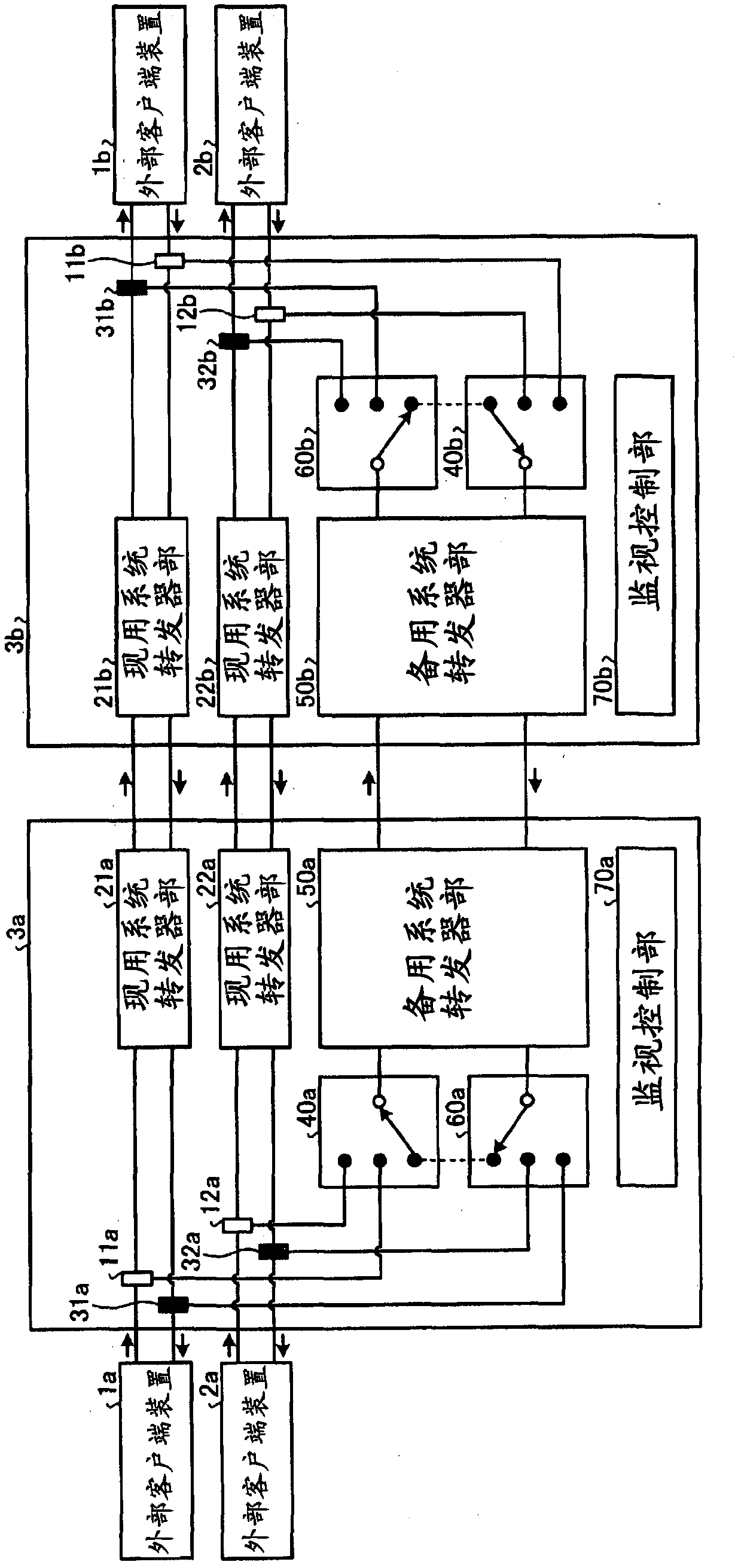
[0032] figure 1 It is a diagram showing a configuration example of an optical transmission network including an optical transmission device according to the present invention. The optical transmission network includes external client devices 1a, 1b, 2a, 2b, and optical transmission devices 3a, 3b. The external client devices 1a, 1b, 2a, and 2b are devices connected to the optical transmission devices 3a and 3b, and provide data transfer between opposing external client devices. The optical transmission devices 3a, 3b transmit and receive optical signals to and from opposing devices (optical transmission devices), and relay communications between the external client devices 1a, 1b and communications between the external client devices 2a, 2b. For example, when the external client device 1a sends data, the optical transmission device 3a forwards the data to the optical transmission device 3b after receiving it, and the optical transmission device 3b forwards the data to the ext...


PUM


Abstract

An optical transmission apparatus that protects different types of signals with a common backup transponder. The optical transmission apparatus includes working transponder units that relay respective optical signals on corresponding working transmission lines to or from external client devices, a backup transponder unit that can relay optical signals of different interface types, a 3:1 optical switch unit and a 1:3 optical switch unit that connect the external client devices and the working transponder units, and can connect the external client device and the backup transponder unit, and a monitor control unit that monitors occurrence of a failure in the working transponder units and the backup transponder unit, and controls switching of the transmission lines upon detection of a failure.

Description

technical field [0001] The invention relates to an optical transmission device with redundant switching function. Background technique [0002] Conventionally, an optical transmission device having a redundant switching function has N active system transponders and backup system transponders. In an optical transmission device, when a signal from a client device, such as an STM (Synchronous Transport Module, Synchronous Transport Module)-64 signal is input, the current system transponder sends an optical signal to the opposite device (optical transmission device). In the opposite device, the active system transponder that receives the optical signal converts it into an STM-64 signal and sends it out to the client device. Usually, the optical transmission device forwards the signal from the client device via the active system transponder when there is no obstacle in the active system transponder. If the active system transponder fails and an obstacle is detected by the own d...

Claims


Application Information

Patent Timeline
IPC IPC(8): H04B10/02H04B1/74H04B10/00H04J14/08H04L12/46H04L29/14H04B10/03H04B10/032H04B10/07H04B10/29H04B10/291H04L69/40
CPCH04Q2011/0081H04L69/40H04J14/0297H04Q11/0062
Inventor 堀内荣一吉田聪太久保和夫
Owner MITSUBISHI ELECTRIC CORP
Learn More