Heat processing apparatus for workpiece

A technology for heat treatment devices and workpieces, applied in heat treatment furnaces, heat treatment equipment, quenching devices, etc., can solve the problems of low processing capacity, unbalanced processing time, etc.

Active Publication Date: 2014-08-13
NETUREN CO LTD
View PDF6 Cites 0 Cited by
  • Summary
  • Abstract
  • Description
  • Claims
  • Application Information

AI Technical Summary

Problems solved by technology

Therefore, the processing time of the shaft portion and the processing time of the cup-shaped body are unbalanced, and the processing time per workpiece is the same as the time required for the heat treatment of the cup-shaped body, and the processing capacity is low.

Method used


Image

  • Heat processing apparatus for workpiece
  • Heat processing apparatus for workpiece
  • Heat processing apparatus for workpiece

Examples


no. 1 Embodiment approach

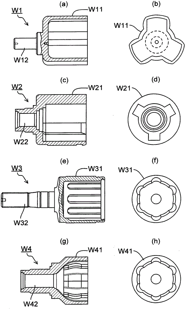
[0147] Heat treatment device 1 with figure 1 The four types of shells shown are the workpieces to be processed. The cup-shaped body is held downward to perform heat treatment on the inner surface of the cup-shaped body and the outer surface of the rod shaft or the inner surface of the cup-shaped body and the hole surface of the cylinder shaft, so the cup-shaped body is called the lower part of the workpiece, and the rod shaft is called the lower part of the workpiece. The upper part or the cylindrical shaft part is called the upper part of the workpiece.

[0148] overall composition

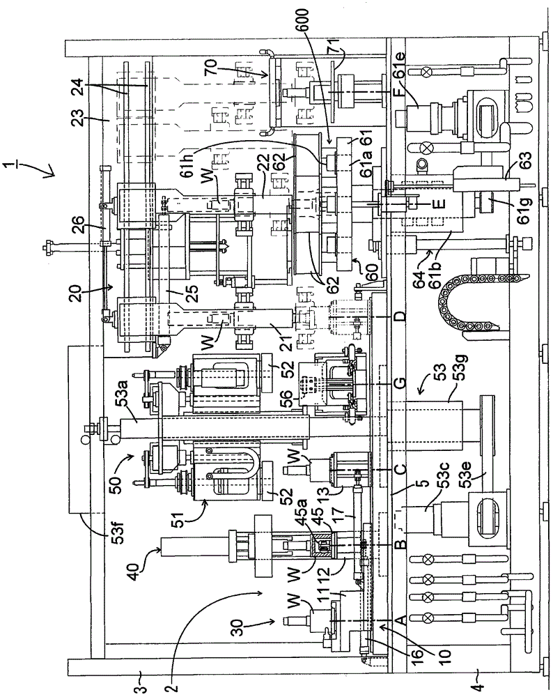
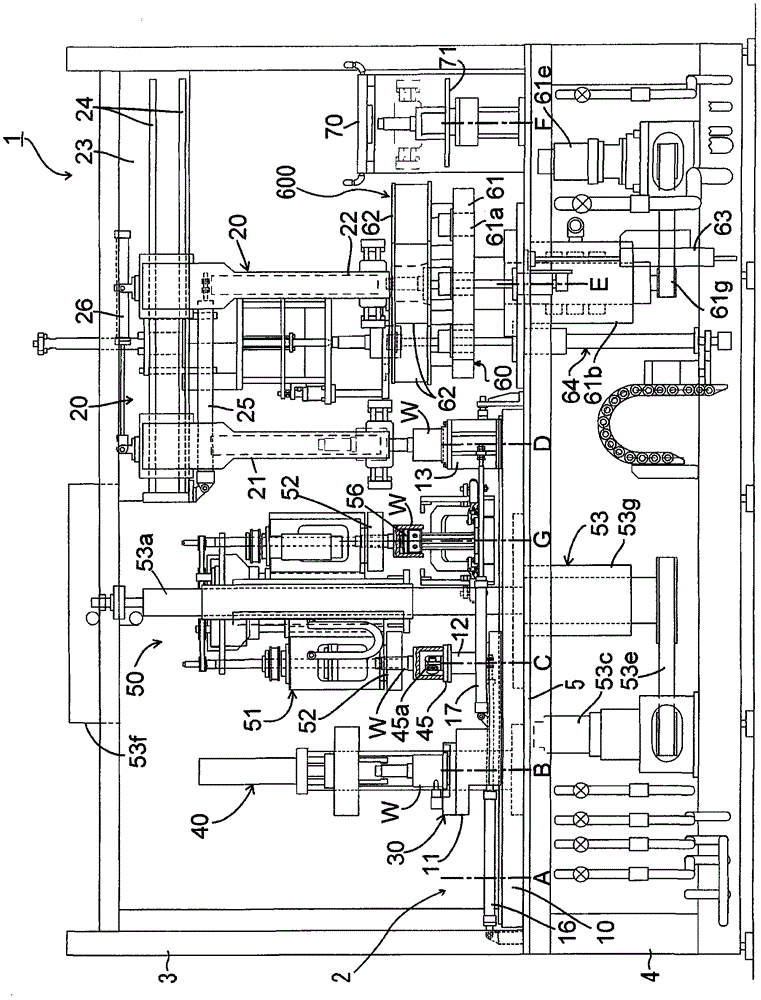
[0149] Such as figure 2 , image 3 , Figure 5 , Figure 6 As shown, the heat treatment apparatus 1 has a table-type conveying mechanism 10 at the front of the left side and a hanger-type conveying mechanism 20 at the front of the right, and conveys the workpiece W from left to right. The heat treatment device 1 includes: a provisional phase determination mechanism 30 for provisional pha...

no. 2 Embodiment approach

[0494] Figure 42 It is a thermal processing head of another embodiment, (a) is a perspective view seen from upper right, (b) is a perspective view seen from upper left, (c) is a top view which shows the connection with a power supply part.

[0495] The heat treatment head 301 of this embodiment includes: a heating coil 310 ; a powered terminal 320 disposed at one end of the heating coil 310 ; and another powered terminal 330 disposed at the other end of the heating coil 310 .

[0496] The heating coil 310 is produced by bending a copper hollow tube or the like. The shape of the heating coil 310 is determined by the shape of the workpiece and the area to be heat-treated, and is not limited to Figure 42 status shown. That is, part of the heating coil 310 has a shape that can approach a portion to be heated that is a portion to be heat-treated of a workpiece (not shown). By passing an alternating current through the portion of this shape, an eddy current is induced in the po...

no. 3 Embodiment approach

[0508] Figure 43 (a) is a perspective view seen from the upper right, (b) is a perspective view seen from the upper left, (c) is a top view which shows the connection with a power supply part, and shows the thermal processing head 301A of still another embodiment. The heat treatment head 301A includes a heating coil 310 and a pair of power supply terminals 320 and 330A. A terminal 320 to be fed is provided at one end of the heating coil 310 , and a terminal 330 to be fed is provided at the other end of the heating coil 310 .

[0509] The terminal 320 to be powered is configured in the same manner as in the other embodiment described above, and has a hollow portion 321 , a hole 322 , and a cooling water inlet 323 . The configuration of the terminal 330A to be fed is different from that of the terminal 330 of the first embodiment. Powered terminal 330 in the first embodiment has hollow portion 331 , hole 332 , and cooling water outlet 333 , but powered terminal 330A in this e...


PUM


Abstract

The invention provides a heat processing apparatus used for the heat treatment of a workpiece, wherein the rod shaft part of the upper portion of a workpiece or the cup-shaped body of the lower portion of the workpiece is subjected to heat treatment by the heat processing apparatus. The heat processing apparatus comprises a temporary phase determination mechanism, a formal phase determination mechanism, a workpiece lower portion heat treatment part and a workpiece upper portion heat treatment part. The heat processing apparatus also comprises one ore more than two of the following members: a desk type conveying mechanism and a suspension bracket type conveying mechanism used for confirming the position of a workpiece or a centering abutting member; a processing component symmetrically equipped with rotary clamping mechanisms with respect to a rotary shaft; a heat treatment head for fixing a fixed base at a predetermined position and connected with a workpiece cooling water pathway; a heating coil for connecting a powered terminal and a power supply terminal and connected with the workpiece cooling water pathway; a workpiece upper portion heating unit for fixing the heating coil of the rod shaft part and the heating coil of the cylinder shaft part at different layers; a rotary cooling device for cooling a workpiece during rotation; and a locking construction for preventing the driving of a heat treatment production line when the locking of an open-close door is unlocked.

Description

technical field [0001] The present invention relates to a heat treatment device for workpieces subjected to heat treatment such as quenching and tempering. Background technique [0002] An outer race of a constant velocity joint can be cited as a specific example of a workpiece to be heat-treated at a plurality of locations. The housing includes a cup-shaped body with one end open, and a shaft portion (solid shaft) integrally protruding from the cup bottom-side end surface of the cup-shaped body or a cylindrical shaft portion protruding from the cup bottom-side end surface. In order to add mechanical strength to the housing, the inner surface of the cup-shaped body is quenched and tempered, and the outer surface of the rod shaft portion or the spline hole of the barrel shaft portion is quenched and tempered. [0003] Such as figure 1 As shown, the shell can be roughly divided into four types. And the enclosures come in a variety of sizes. [0004] figure 1 Case W1 shown...

Claims


Application Information

Patent Timeline
Patent Type & Authority Patents(China)
IPC IPC(8): C21D9/00C21D1/10C21D1/62
CPCC21D1/10C21D1/62C21D9/00Y02P10/25
Inventor 小池胜登细川明宏中村晴宣中岛荣木田树志荒井克宜
Owner NETUREN CO LTD
Why Eureka
Try Eureka