Floating wheel type water turbine

One-type water turbine, the technology of water turbine, applied in the direction of water wheel, reaction engine, mechanical equipment, etc., can solve the requirements of equipment manufacturing process and technical design, high manufacturing cost, buoyancy traction device occupying water area, blade water interception area is small, etc. problems, to achieve the effect of increasing the intercepting area of ​​the flowing water, omitting the buoyancy traction device, and improving the conversion efficiency

Inactive Publication Date: 2012-02-08
杨春义
View PDF0 Cites 14 Cited by
  • Summary
  • Abstract
  • Description
  • Claims
  • Application Information

AI Technical Summary

Problems solved by technology

[0003] CN1601079A, CN 03100881X, CN 1834452A, and CN201090360Y disclose the technology of using natural water flow to generate electricity, and their common point is to provide a kind of independent buoyancy traction device, water wheel, speed change mechanism, generator and other components to form a whole with it, so that The setting can make the system float naturally with the fluctuation of the river water, so as to ensure that its operation will not be affected; however, the above-mentioned system has the following disadvantages: firstly, the energy conversion rate is low, and the weight of the water wheel itself will cause reactive power loss; secondly The water interception area of ​​the blades of the water wheel is relatively small, and its buoyancy traction device will occupy a part of the water area; in addition, the weight of the water wheel itself will increase the wear of the iron, resulting in operating costs; The size limitation and inconvenience in the design can be folded, and at the same time, the complex equipment manufacturing process and technical design requirements will cause high manufacturing costs

Method used


Image

  • Floating wheel type water turbine
  • Floating wheel type water turbine
  • Floating wheel type water turbine

Examples


Embodiment Construction

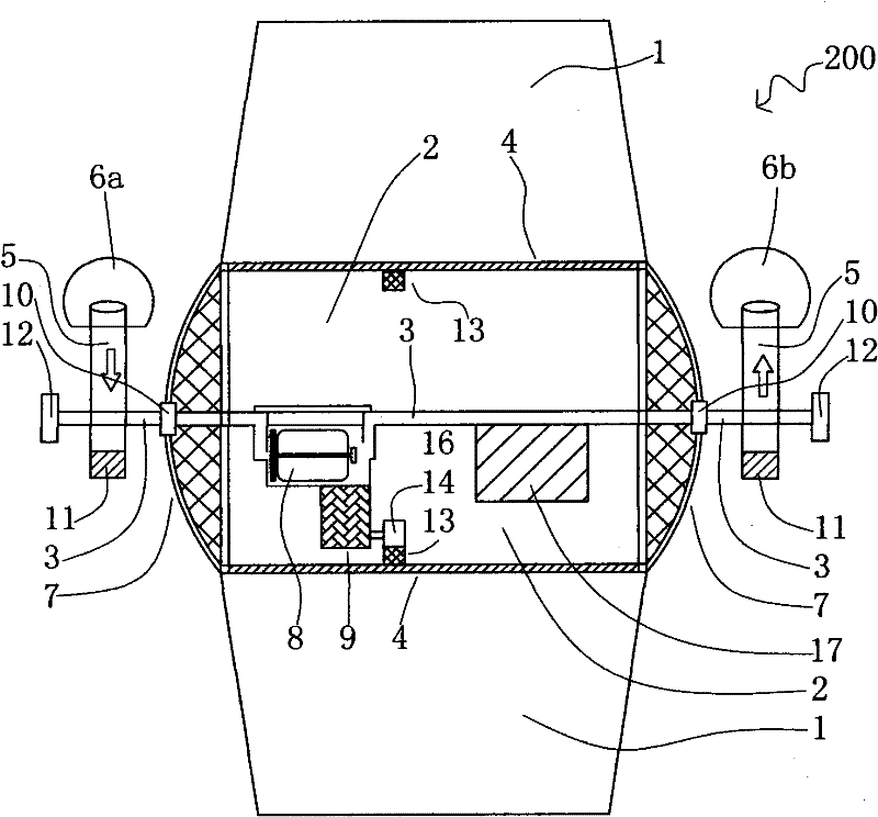
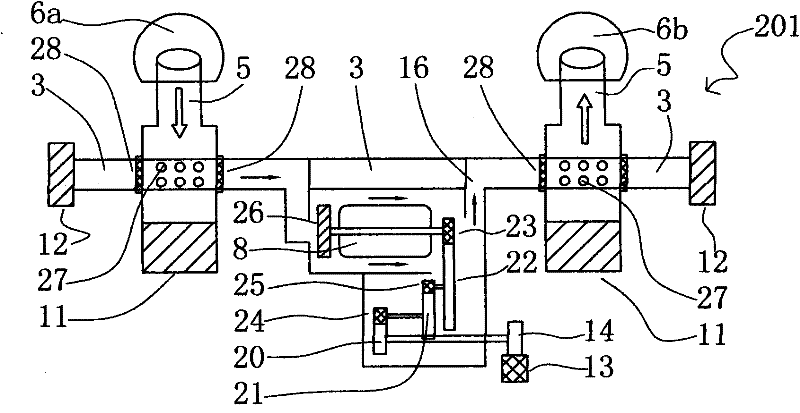
[0051] Figure 1 to Figure 14 It is an explanatory drawing of the built-in water turbine of this invention.

[0052] now refer to Figure 1 to Figure 14 .

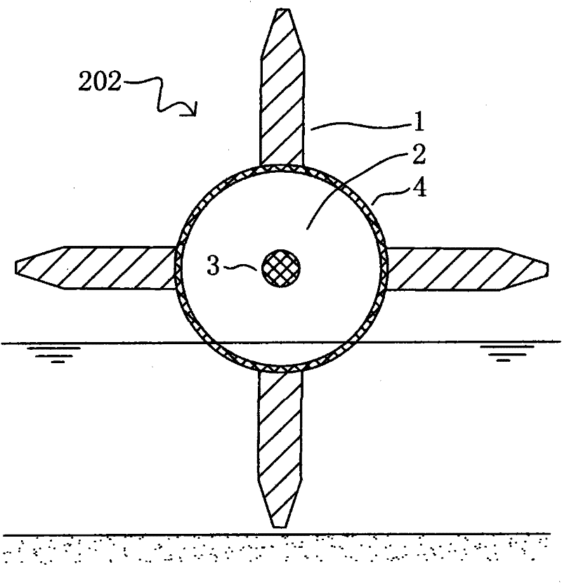
[0053] image 3 It is the water wheel 202 of the present invention, including blade 1, buoy 2, shaft core 3 and housing 4; as Figure 5 As shown, in order to adapt to different water depths and facilitate the adjustment of the draft of the water wheel 202, the blades 1 are of modular design, respectively A, B, C, and D, and the last piece of A cut surface is conical; The slots are received and each module is fixed and integrated by bolts 37; the blade 1 is also provided with a plurality of independent sealed cavities 38, one of the purpose of setting the cavities 38 is to provide buoyancy support for the system, and its design principle is: taking into account the blade 1 One is that the cavity must be independent, so that even if a part of the cavity is damaged and leaks, the system will not be paralyzed; the other is...


PUM


Abstract

The invention relates to a water turbine used for operations such as hydroelectric power generation, water pumping and the like by using nature water flow and low water head. The water turbine is characterized in that a water wheel is composed of a floating barrel and blades provided with independent seal cavities, the water wheel rotates by absorbing water energy so as to provide power for the water turbine and generally provide buoyant force support for the water turbine simultaneously; and the water turbine is divided into a built-in type water turbine and an external type water turbine and the main difference between the two types of water turbine is that a generator, a gear case and the like are placed inside or outside the floating barrel. The water turbine provided by the invention has the advantages of low manufacturing cost and operating cost and high energy conversion rate, and is applicable to multiple occasions.

Description

technical field [0001] The invention relates to a water turbine, which uses natural water flow and low water head to generate electricity, pump water, etc. Background technique [0002] In a hydropower station, an artificial dam is used to store water to form a water drop, and then the potential energy of the water acts on the water wheel to rotate, and the water wheel then drives the generator to generate electricity and rotate to complete power generation. This type of power generation has the advantages of large capacity and low environmental pollution, but it also has the disadvantages of large project investment, complex construction, long construction period, and dam construction is easily restricted by natural hydrological conditions. Therefore, the water energy in vast natural rivers cannot be fully utilized. Utilization can only be wasted in vain. [0003] CN1601079A, CN 03100881X, CN 1834452A, and CN201090360Y disclose the technology of using natural water flow to...

Claims


Application Information

Patent Timeline
Patent Type & Authority Applications(China)
IPC IPC(8): F03B13/08F03B7/00F03B3/12F03B17/02E02B9/00E02B7/02
CPCY02E10/22Y02E10/20Y02E10/223
Inventor 杨春义
Owner 杨春义
Why Eureka
Try Eureka