Achromatic apparatus for achromatizing achromatic toner image formed on recording medium

A technology of toner image and recording medium, applied in the field of decolorization device, which can solve the problem of paper smoke, etc., and achieve the effect of avoiding discoloration and low power consumption

Inactive Publication Date: 2012-02-08
CASIO ELECTRONICS MFG CO LTD +1
View PDF10 Cites 8 Cited by
  • Summary
  • Abstract
  • Description
  • Claims
  • Application Information

AI Technical Summary

Problems solved by technology

Therefore, even if the power to the heater is turned off, the temperature of the heat radiation from the heater will not drop immediately, but the surface temperature of the paper will rise and the discoloration of the paper will develop.
[0024] Especially in the case of a paper jam, the jammed paper may partially protrude and come close to or in contact with the heat radiating surface of the heater, thus easily causing paper to smoke in this case.

Method used


Image

  • Achromatic apparatus for achromatizing achromatic toner image formed on recording medium
  • Achromatic apparatus for achromatizing achromatic toner image formed on recording medium
  • Achromatic apparatus for achromatizing achromatic toner image formed on recording medium

Examples


Embodiment 1

[0056]

[0057] First, a method for producing a decolorizable toner used in the present invention will be described as Example 1. First, a cyanine-based near-infrared absorbing pigment "IRT" (manufactured by Showa Denko / cf. Figure 17A The structural formula) is 1.5 parts by mass, so that the organoboron compound "P3B" (manufactured by Showa Denko / refer to Figure 17B ) is 4 parts by mass, the polyester binder resin for toner (manufactured by Kao) is 90.5 parts by mass, the negative charge regulator "LR-147" (manufactured by CARLIT, Japan) is 1.5 parts by mass, and Palm WAX1 No. powder (produced by Kato Makoto Co., Ltd.) was 2.5 parts by mass, which were put into a Henschel mixer (manufactured by Mitsui Mining Co., Ltd.) and mixed.

[0058] Then, the above-mentioned mixture was melt-mixed by a twin-shaft stirrer. The thus obtained kneaded material was coarsely crushed by a ROTOPLEX granulator (manufactured by Hosokawa Micron Group) to obtain a coarsely crushed product. Th...

Embodiment 2

[0061]

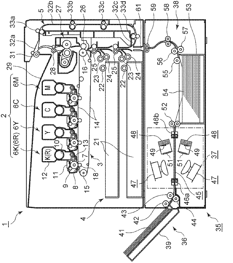
[0062] figure 1 It is a cross-sectional view schematically showing the internal structure of an image forming apparatus with a decolorizing function (hereinafter simply referred to as a printer) provided with decolorizing devices in series according to Embodiment 2 of the present invention. figure 1 The illustrated printer 1 is a tandem color image forming apparatus of an electronic phototype and a secondary transfer method, and an image forming unit 2 is composed of an intermediate transfer belt unit 3 , a paper feeding unit 4 , and a conveyance unit 5 for double-sided printing. .

[0063] The above-mentioned image forming unit 2 is configured by arranging four image forming units 6 (6M, 6C, 6Y, 6K (6R)) in parallel in multiple stages from the right side to the left side in the figure.

[0064]The image forming unit 6R is used for the decolorizable toner R obtained in Example 1, and can be replaced with the image forming unit 6K for the black toner K. The image f...

Embodiment 3

[0174] Figure 13 It is a cross-sectional view showing the structure of the decolorizing unit (decolorizing unit) 150 of the decolorizing device of the third embodiment. In addition, the overall structure of the decolorizing device is the same as figure 1 The structure in the shown decolorizing device 35 is the same, and the basic structure is the same as Figure 4 The decolorizing unit 37 shown is the same. Thus, in Figure 13 in, right with figure 1 , Figure 4 The same structural parts are denoted by the same reference numerals.

[0175] Such as Figure 13 As shown, in the decolorizing unit 150 of the decolorizing device of this embodiment, a large change is applied to the heat radiation heater unit. That is, the heat radiation heater part 151 (151a, 151b) of the decolorizing part 150 of this embodiment is equipped with the 1st heat insulating part 153 first, and this 1st heat insulating part 153 is exposed to the heat from the outside. Figure 4 The portion of the ...


PUM


Abstract

An achromatic apparatus achromatizing an achromatic toner image on paper by an achromatic toner containing a near-infrared ray absorbing colorant that is a cyanine dyes, and an organic boron-based compound includes heater units each of which is a ceramic heater arranged across an achromatic convey path of an achromatic unit, and light source units each of which includes an LED array chip having a center wavelength shifted to the long-wavelength side from the peak of the first absorption band of the near-infrared ray absorbing colorant and within a predetermined wavelength range from 820 to 850 nm. While the paper formed with the achromatic toner image is being conveyed through the achromatic convey path at a liner speed equal to or faster than 15 mm / sec, the achromatic toner image is heated to a predetermined temperature of 140 DEG C, and is irradiated with achromatic light from the LED, and thus achromatized efficiently at a low energy consumption. The achromatic apparatus also comprises a heat insulation structure intercepting convection between a thermal radiation space and external world caused by a heat source and a rotary driving mechanism enabling the heater units to retreat when unexpected unfavorable circumstances emerge.

Description

[0001] Cross-references to related applications: This application claims Japanese patent application 2010-163464 filed on July 21, 2010, Japanese patent application 2010-178770 filed on August 9, 2010, Japanese patent application filed on December 6, 2010 Patent application No. 2010-271130 and Japanese patent application No. 2010-277836 filed on December 14, 2010 are based on priority rights, and the contents of these basic applications are incorporated in this application in their entirety. technical field [0002] The present invention relates to a decolorizing device for decolorizing a decolorizable toner image formed on a recording medium with a decolorizable toner containing cyanine dyes. ) composed of a near-infrared absorbing pigment and an organic boron compound, and relates to a decolorizing device for decolorizing the above-mentioned decolorable toner image with low energy consumption and under optimal decolorizing conditions. Background technique [0003] In recen...

Claims


Application Information

Patent Timeline
Patent Type & Authority Applications(China)
IPC IPC(8): G03G21/00
CPCB41M7/0009G03G15/1665G03G15/6558G03G15/6585G03G21/00
Inventor 三井乡史前田克己玉川洋一
Owner CASIO ELECTRONICS MFG CO LTD
Why Eureka
Try Eureka