
Method and apparatus for depositing film in fiber by using atmospheric pressure glow discharge

A technology of glow discharge and atmospheric pressure, applied in the field of plasma, can solve the problems of difficulty in depositing thin films of optical fibers and high vacuum cost, and achieve the effects of improving transmission efficiency, low equipment cost, and low gas flow

Active Publication Date: 2013-06-12
DALIAN NATIONALITIES UNIVERSITY
View PDF2 Cites 0 Cited by
  • Summary
  • Abstract
  • Description
  • Claims
  • Application Information

AI Technical Summary

Problems solved by technology

The use of traditional plasma deposition has problems such as high vacuum cost and difficulty in depositing thin films inside optical fibers. So far, there has been no report on the deposition of fluorocarbon thin films in optical fibers.

Method used


Image

  • Method and apparatus for depositing film in fiber by using atmospheric pressure glow discharge
  • Method and apparatus for depositing film in fiber by using atmospheric pressure glow discharge

Examples


Embodiment Construction

[0022] The present invention will be further described below in conjunction with drawings and embodiments.

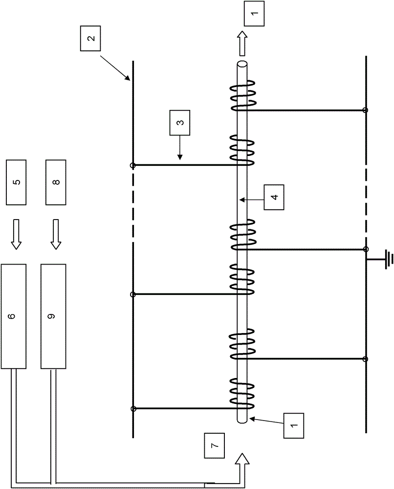
[0023] Devices for depositing thin films in optical fibers using atmospheric pressure glow discharge, such as figure 1 As shown, the discharge plasma chamber, that is, the inside of the optical fiber 1 is under atmospheric pressure conditions. The AC sine wave high-voltage power supply 2 used to generate plasma is connected to the high-voltage electrode 3 , the peak-to-peak voltage reaches over 20KV, and the frequency ranges from 5KHZ to 15KHZ. After high-voltage discharge, plasma 4 is generated in the fiber tube. The distance between the high-voltage electrode and the low-voltage electrode is adjusted between 3 and 5 cm. The optical fiber tube is used as the deposition substrate, and the active material generated by the plasma is deposited on the inner wall of the optical fiber to change the optical density of the optical fiber. Before deposition, use helium 5 as the...


PUM


Abstract

The invention relates to a method and apparatus for depositing a film in a fiber by using atmospheric pressure glow discharge. According to the invention, electrodes with alternate high voltage and low voltage are uniformly wound on the outer wall of an optical fiber tube, and, with the inner wall of the optical fiber tube as a deposition substrate, a fluorocarbon film is deposited on the inner wall by using fluorocarbon gas under the condition of atmospheric pressure so as to improve transmission efficiency and anti-oxidation of the fiber. In the invention, dielectric barrier plasma discharge is employed for deposition of the film, so the invention has the following unique advantages: a simple discharge mode, low cost for equipment, small gas volume, low gas flow and low energy consumption.

Description

technical field [0001] The invention relates to the technology of using dielectric barrier discharge plasma, in particular to a method and device for depositing thin films in optical fibers by using atmospheric pressure glow discharge. Background technique [0002] Optical fiber, that is, optical fiber, is a kind of glass fiber with high transparency and thickness like spider silk. When light enters the glass fiber at a suitable angle, the light will travel along the curved glass fiber. Because this fiber can be used to transmit light, it is called an optical fiber. Optical fibers can send sunlight to every corner, and can also be used for mechanical processing, computers, robots, automotive switchboards, etc. have also successfully used optical fibers to transmit light sources or images. If combined with sensitive elements or using its own characteristics, it can be made into various sensors to measure pressure, flow, temperature, displacement, gloss and color, etc. It is...

Claims


Application Information

Patent Timeline
Patent Type & Authority Patents(China)
IPC IPC(8): C03C25/22C03C25/42
Inventor 刘东平
Owner DALIAN NATIONALITIES UNIVERSITY
Learn More