
Solar air heat collection device with fluctuant strip fins

A technology of air heat collection and solar energy, which is applied in the field of solar heat collection equipment and air heat collection devices, which can solve the problems of expensive thermal insulation materials or light-transmitting materials, limited efficiency improvement, and increased cost of heat collection devices, so as to improve efficiency , uniform flow field, optimized flow field effect

Inactive Publication Date: 2012-02-15
TSINGHUA UNIV
View PDF4 Cites 7 Cited by
  • Summary
  • Abstract
  • Description
  • Claims
  • Application Information

AI Technical Summary

Problems solved by technology

For the first way to reduce heat loss, many air heat collecting devices are mostly implemented by increasing the thickness of the frame insulation layer or using honeycomb light-transmitting panels (application (patent) number: 85200928, semi-honeycomb double-return solar air heat collecting device) However, some thermal insulation materials or light-transmitting materials are more expensive, resulting in an increase in the cost of the final heat collection device; for the second way to reduce heat loss, most heat collection devices increase the speed of the fan, use spoilers, baffles ( Patent application number: 200710195030, baffle type double-effect heating solar air heat collection device) or double-layer air duct (patent application number: 200720034396, solar air heat collection device) and other methods, although this approach is helpful to improve efficiency , but the efficiency improvement is limited
In addition, increasing the flow rate will increase the power consumption to a certain extent, which will increase the operating cost

Method used


Image

  • Solar air heat collection device with fluctuant strip fins
  • Solar air heat collection device with fluctuant strip fins
  • Solar air heat collection device with fluctuant strip fins

Examples


Embodiment Construction

[0015] The working principle and specific structure of the present invention will be further described below in conjunction with the accompanying drawings.

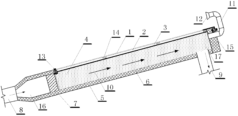
[0016] The working principle of the solar air heat collection device is to use solar radiation heat to pass through the transparent cover plate 1 to heat the heat collector plate 2, and then heat the air flowing through the heat collector plate 2 through convective heat exchange.

[0017] figure 1 Structural schematic diagram of the solar air heat collecting device provided by the present invention, the solar air heat collecting device includes a transparent cover plate 1, a heat collecting plate 3, an air inlet pipe 8, an air outlet pipe 9, an air inlet 16, an air outlet 17, The back plate 5 and the side plate 15; the back plate 5 and the side plate 15 are provided with a thermal insulation board 6; the airtight air layer 2 is formed between the light-transmitting cover plate 1 and the heat collecting plate 3, and the de...


PUM


Abstract

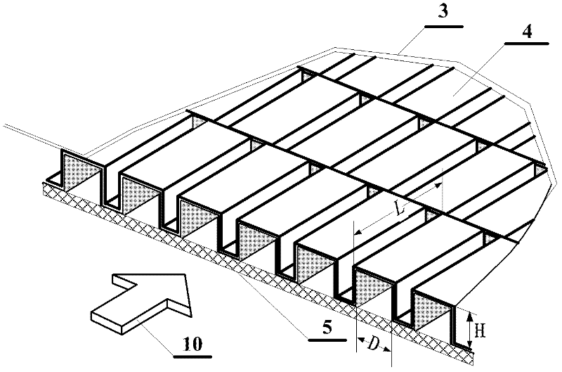
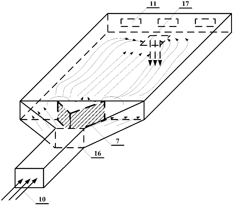
The invention relates to a solar air heat collection device with fluctuant strip fins and belongs to the technical fields of solar utilization and energy conservation of buildings. The device comprises a transparent cover plate, a heat collecting pipe, a vent pipe, a sealed air layer and an air circulation channel. At least two groups of strip fins are arranged in the air circulation channel along the air circulating direction; two adjacent groups of strip fins are staggered; the cross sections of each group of strip fins have fluctuant sawtooth shapes; and a flow guide structure is arranged close to an air inlet in the air circulation channel. The solar air heat collection device greatly increases a heat exchange area between air and the heat collecting plate through the strip fins, improves heat exchanging efficiency, and optimizes the flow field of the air circulation channel through the flow guide structure. In the device, all components are made of common materials by common production processes, so that the device has the advantages of simple process, low cost and the like. The solar air heat collection system can be used in the fields of solar low temperature heat utilization such as heating, drying and the like, has low cost, is convenient to operate and maintain and has a wide application prospect.

Description

technical field [0001] The invention relates to a solar heat collecting device, in particular to an air heat collecting device which uses solar radiation heat to heat air, and belongs to the technical field of solar energy utilization and building energy saving. Background technique [0002] Today, when traditional energy sources (such as coal, oil, etc.) are increasingly tense, renewable energy sources (such as solar energy, wind energy, water energy, biomass energy, etc.) have made great progress as alternative energy sources. In the northern part of my country, there is abundant sunshine, which belongs to the I, II, and III areas of solar energy utilization ([1] Chris C.S.Lau, Joseph C.Lam, Liu Yang, Climate classification and passive solar design implications in China, Energy Conversion & Management, 2007: 2006-2015), so solar energy utilization has a good development prospect in the northern region. Due to the cold climate in northern my country and the high energy cons...

Claims


Application Information

Patent Timeline
Patent Type & Authority Applications(China)
IPC IPC(8): F24J2/22F24J2/46F24J2/48F24S10/55
CPCY02E10/44
Inventor 杨旭东杨铭王鹏苏单明
Owner TSINGHUA UNIV
Learn More