Method for drying irregular ceramic plates and rods

A drying method and technology of ceramic plates, which are applied in the direction of static material dryers, partial agitation dryers, drying, etc., can solve the problems of restricting the drying of special-shaped ceramic plates and pottery sticks, affecting the surface quality, and rubbing of rollers, etc., so as to reduce Effects of drying and cracking, solving deformation and cracking, and improving pass rate

Inactive Publication Date: 2012-02-15
JIANGSU CN ECO MATERIALS CO LTD
View PDF5 Cites 8 Cited by
  • Summary
  • Abstract
  • Description
  • Claims
  • Application Information

AI Technical Summary

Problems solved by technology

The special-shaped ceramic plates and pottery sticks are formed by extrusion. After forming, the water content of the wet billet is 13-18wt%, and one side is placed flat on the roller kiln

Method used


Image

  • Method for drying irregular ceramic plates and rods
  • Method for drying irregular ceramic plates and rods
  • Method for drying irregular ceramic plates and rods

Examples


Embodiment 1

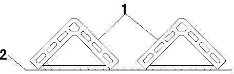
[0018] Embodiment 1: see figure 1 , place the corner ceramic plate 1 with an extruded moisture content of 15wt% (the product specification is 900*150*150mm), place it on the epoxy resin plate 2 with holes in an inverted "V" shape (triangle) according to the figure, and put it into the closed In the box-type drying room, dry for 48 hours according to the temperature, humidity, and time curves in Table 1. During the low-temperature and high-humidity drying period, the initial temperature and high-humidity drying time is 3-3.5 times the subsequent drying time; the high-temperature and high-humidity drying period, the final high temperature The low humidity drying time is 2.5-3.0 times of the previous drying time.

Embodiment 2

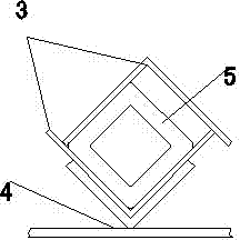
[0019] Example 2: see figure 2 Put the extruded cubic pottery 5 with a moisture content of 15wt% (the product specification is 1500*50*50mm), put it in a movable frame composed of two right-angled aluminum alloys (or stainless steel and other non-rusting metals) 3, and place the whole on Put it on the "v" shaped bracket 4 with plane support, put it into a closed box-type drying room, and dry it for 18 hours according to the temperature, humidity, and time curves in Table 1. 3-3.5 times the drying time; during the high-temperature and high-humidity drying period, the final high-temperature and low-humidity drying time is 2.5-3.0 times the previous drying time.

Embodiment 3

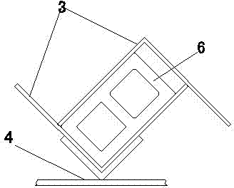
[0020] Embodiment 3: see image 3 Put the extruded shuttle-shaped louver pottery 6 with a moisture content of 15wt% (the product specification is 1200*90*50mm), put it in the movable frame of two right-angled aluminum alloys 3, and put it on the "v" with plane support as a whole. "shaped bracket 4, put it in a closed box-type drying room, and dry it for 30 hours according to the temperature, humidity, and time curves in Table 1. During the low-temperature and high-humidity drying period, the initial temperature and high-humidity drying time is 3-3.5 times the subsequent drying time. times; during the high temperature and high humidity drying period, the final high temperature and low humidity drying time is 2.5-3.0 times the previous drying time.

[0021] See Table 2 for comparison between drying by the method of the present invention and drying in the prior art.


PUM


Abstract

The invention discloses an improved method for drying irregular ceramic plates and rods which are used for external wall decoration. The method is characterized by comprising the steps of: placing the irregular ceramic plates and rods onto a support in a manner that cross section are place in an inverted V-shape or a V-shape, and drying in a heat-insulation and moisture-preservation environment for 16-48 hours in total by using a temperature rise and moisture decrease drying process specifically according to a long time interval with the high humidity of 60-100% at 25-50 DEG C at first, then a short time interval with the medium humidity of 30-59% at 51-80 DEG C, and then a medium time interval with the low humidity of 0-29% at 81-150 DEG C. According to the method disclosed by the invention, the problems of deformation and cracking of the irregular ceramic plates and rods in a drying process are solved simply and conveniently, the drying qualification rate of green bodies can be increased by 30-60% compared with the original drying qualification rate, and the surface quality of dried products can be ensured.

Description

technical field [0001] The present invention improves the drying method of special-shaped ceramic plates (such as corner ceramic plates) and pottery sticks (such as cubic pottery and shuttle-shaped venetian pottery) used for exterior wall decoration. By changing the drying arrangement and drying system, the occurrence of defects in the drying process can be greatly reduced. Background technique [0002] Ancillary products of dry-hanging ceramic panels for exterior wall decoration - special-shaped ceramic panels (corner ceramic panels) and pottery sticks (cubic pottery, shuttle-shaped venetian pottery, etc.), shaped like figure 1 , 2 , 3. The prior art adopts the usual ceramic drying method, and the product is placed flat on one side and put into a roller-type drying kiln to dry together with other ceramic products. Since this type of product is characterized by a large ratio of length to width (7-30), complex cross-sectional structure, and high cross-sectional height (50-1...

Claims


Application Information

Patent Timeline
IPC IPC(8): F26B9/10C04B33/30
Inventor 倪曌青王维成
Owner JIANGSU CN ECO MATERIALS CO LTD
Why Eureka
Try Eureka