Laser radar optical system with optical axis calibrating function and optical axis calibrating method

A laser radar and optical system technology, applied in radio wave measurement systems, instruments, etc., can solve the problems of complex operation and external auxiliary devices, and achieve the effects of simple operation, high optical axis calibration accuracy, and convenient use.

Inactive Publication Date: 2012-02-15
INST OF APPLIED ELECTRONICS CHINA ACAD OF ENG PHYSICS +1
View PDF4 Cites 51 Cited by
  • Summary
  • Abstract
  • Description
  • Claims
  • Application Information

AI Technical Summary

Problems solved by technology

[0003] In order to overcome the deficiencies in the prior art that laser radar optical system optical axis calibration needs an external auxiliary device and complicated operation, the purpose of the present invention is to prov

Method used


Image

  • Laser radar optical system with optical axis calibrating function and optical axis calibrating method
  • Laser radar optical system with optical axis calibrating function and optical axis calibrating method
  • Laser radar optical system with optical axis calibrating function and optical axis calibrating method

Examples


Example Embodiment

[0025] Example 1

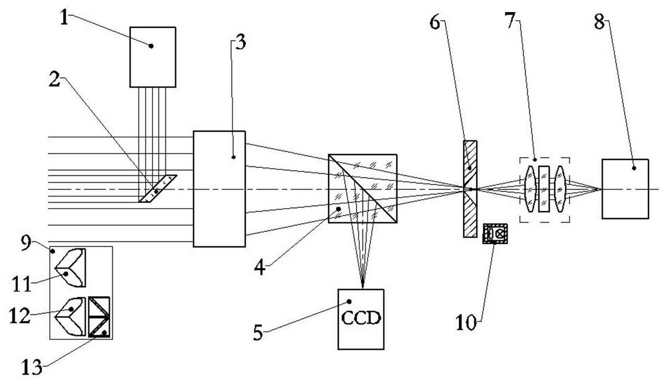
[0026] figure 1 It is a schematic structural diagram of the laser radar optical system with optical axis calibration function of the present invention.

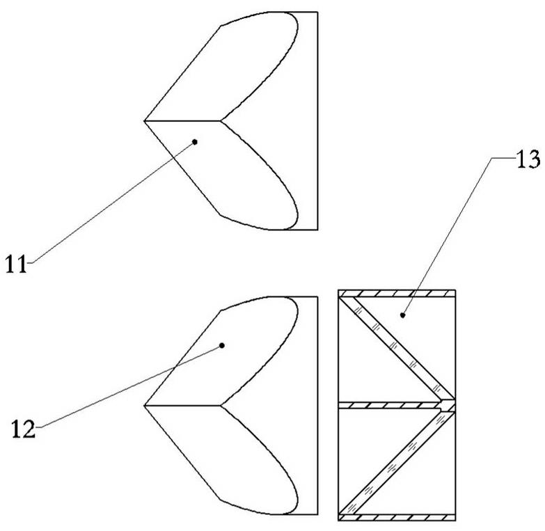
[0027] figure 2 It is a schematic diagram of the structure of the retro-reflecting mirror group in the laser radar optical system with the optical axis calibration function of the present invention.

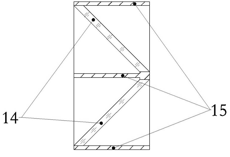
[0028] image 3 It is a schematic structural diagram of the laser attenuator in the laser radar optical system with the optical axis calibration function of the present invention.

[0029] Figure 4 It is a schematic structural diagram of the illumination light source in the laser radar optical system with the optical axis calibration function of the present invention.

[0030] exist Figures 1~4 Among them, the laser radar optical system with optical axis calibration function of the present invention includes a laser 1, a laser emitting mirror 2, a signal receiving optical element 3, a beam splitter 4,...

Example Embodiment

[0041] Example 2

[0042] The basic structure of this embodiment is the same as that of Embodiment 1, except that the light absorption plate 15 set in the laser attenuator 13 is made of graphite material.

Example Embodiment

[0043] Example 3

[0044] The basic structure of this embodiment is the same as that of Embodiment 1, the difference is that the light absorption plate 15 set in the laser attenuator 13 is made of ceramic material.


PUM


Abstract

The invention discloses a laser radar optical system with an optical axis calibrating function and an optical axis calibrating method thereof. A laser emission mirror in the optical system is arranged on an adjusting mechanism which has a pitch angle and an azimuth angle being adjustable accurately and is locked; a retroreflection mirror group is arranged on the outer sides of the laser emission mirror and a signal receiving optical part; and a lighting source is arranged on the outer side between a field diaphragm and a relay lens group. The central position of the field diaphragm representing a laser signal receiving optical axis and the laser far-field spot position representing a laser emission optical axis are successively imaged into a CCD (charge coupled device) camera for detecting a target picture through utilizing a retroreflection characteristic of a pyramid prism in the retroreflection mirror group. The laser emission mirror is adjusted, so that the two positions are coincided in the CCD camera to complete optical axis calibration. The calibrating method disclosed by the invention has high accuracy, is simple to operate, does not rely on an external auxiliary assembly,and is convenient to use.

Description

technical field [0001] The invention belongs to the technical field of laser radar optical devices, and in particular relates to a laser radar optical system with an optical axis calibration function and an optical axis calibration method. It is used for laser transmitting and receiving optical systems such as lidar and laser ranging. Background technique [0002] During the working process of the laser radar optical system, the laser beam is transmitted to the target, and the reflected signal of the target to the laser is received at the same time. The system needs to have the ability to use the CCD camera to image and detect the target. One of the important technical requirements is to ensure the consistency of the laser emission optical axis, the laser signal receiving optical axis, and the target imaging aiming optical axis. The optical axis calibration of the existing laser radar optical system to ensure the consistency of the optical axis mostly needs to be carried ou...

Claims


Application Information

Patent Timeline
IPC IPC(8): G01S7/497
Inventor 叶一东罗佳胡大平田飞田英华王卫民马毅
Owner INST OF APPLIED ELECTRONICS CHINA ACAD OF ENG PHYSICS
Why Eureka
Try Eureka